Air bearing and rotor system

a rotor system and bearing technology, applied in the direction of bearing unit rigid support, machines/engines, liquid fuel engines, etc., can solve the problems of reducing the interference clearance of the bearing and the air bearing, and achieve the effect of reducing the influence of accumulated clearance, reducing the whole size of the system, and smooth operation of the rotor system

Active Publication Date: 2019-06-06
IUCF HYU (IND UNIV COOP FOUNDATION HANYANG UNIV)
View PDF4 Cites 8 Cited by
  • Summary
  • Abstract
  • Description
  • Claims
  • Application Information

AI Technical Summary

Benefits of technology

[0024]According to embodiments of the present invention, the air bearing is provided, in which the portion of the bearing support which directly interfaces with the rotor is made of a rigid body, and the bearing support is supported by the spring and the damper. Therefore, the present invention actively accommodates the geometric deformation of the bearing and/or shaft caused by dynamic instability of the rotor and the heat/rotation thereof, thereby performing the smooth operation of the rotor system under severe operation conditions, such as ultrahigh speed, high temperature and externa

Problems solved by technology

However, there is a limit to the air bearing in that due to expansion of constitutional elements, such as a shaft and a bearing, caused by heat, and expa

Method used


Image

  • Air bearing and rotor system
  • Air bearing and rotor system
  • Air bearing and rotor system

Examples


first embodiment

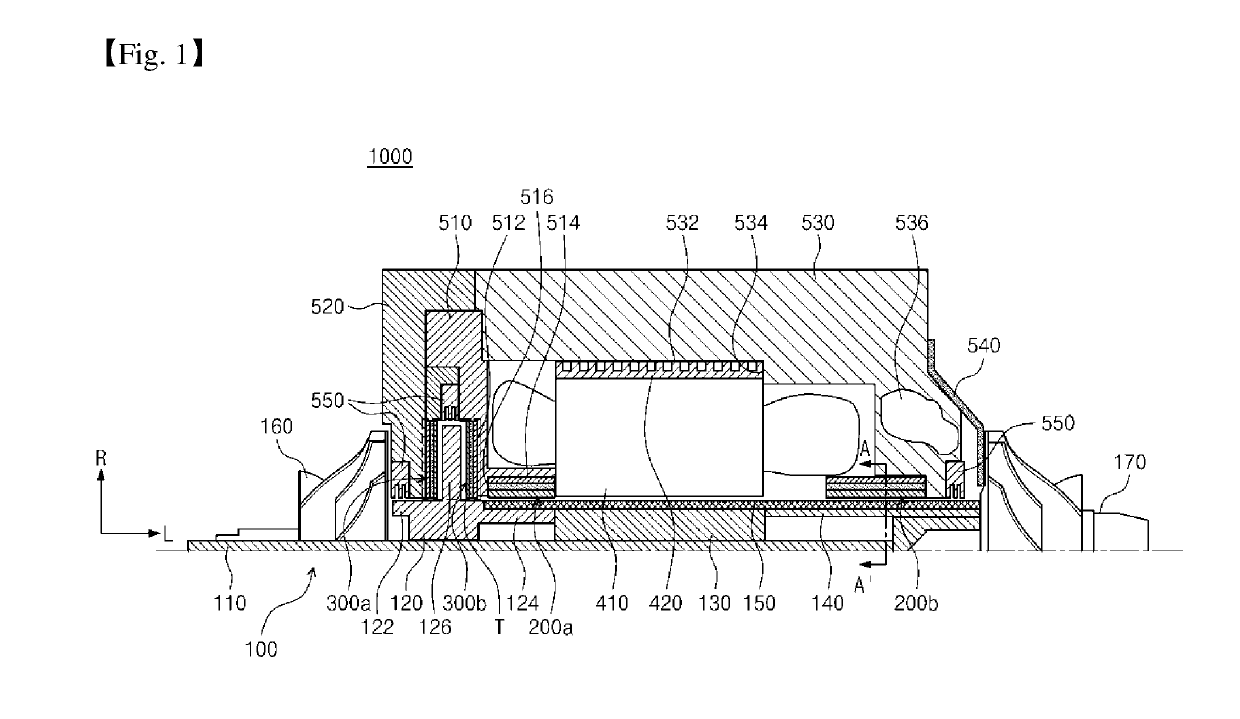
[0038]Referring to FIG. 1, a rotor system 1000 according to the present invention may include at least one of a rotating shaft structure 100, air bearings 200a, 200b, 300a and 300b for supporting rotation of the rotating shaft structure 100, and housings 510, 520 and 530. Also, the rotor system 1000 may further include a stator 410 for providing a rotating force to the rotating shaft structure 100 or generating an electric current corresponding to a rotating force of the rotating shaft structure 100. Hereinafter, each configuration will be described in detail. FIG. 1 shows an upper end of the rotor system 1000 when seen from the longitudinal cross-sectional view, while since the configuration of a lower end is symmetrical to that of the upper end, the detailed illustration and description will be omitted herein.

[0039]Rotating Shaft Structure 100

[0040]The rotating shaft structure 100 is a rotatably structure which is inserted in a hollow portion of the rotor system 1000 according to ...

second embodiment

[0095]FIG. 5 is a partially cross-sectional view illustrating the rotor system 2000 according to the present invention.

[0096]Referring to FIG. 5, the rotor system 2000 according to the second embodiment of the present invention may include at least one of a rotating shaft structure 1100, air bearings 1200a, 1200b, 1300a and 1300b for supporting rotation of the rotating shaft structure 100, and housings 1510, 1520 and 1530. Also, the rotor system 1100 may further include a stator 1410 for providing a rotating force to the rotating shaft structure 1100 or generating an electric current corresponding to a rotating force of the rotating shaft structure 1100.

[0097]The first embodiment is substantially identical to the second embodiment, except for the internal arrangement, and thus the detailed description for the same configurations will be omitted herein.

[0098]In the rotor system 2000 according to the second embodiment, the first rotating impeller 1160, the first journal air bearing 12...


PUM


Abstract

Provided is a rotor system including: a rotating shaft structure including a shaft and a thrust disc formed in a radial direction of the shaft; at least one journal air bearing including a journal bearing support which is made of a rigid body to support a load applied to the shaft by air, a journal spring which encloses an outer surrounding surface of the journal bearing support to provide a elastic support force to the journal bearing support, and a journal damper which encloses the outer surrounding surface of the journal bearing support to dissipate energy from vibration applied to the journal bearing support; and at least one thrust air bearing including a thrust bearing support which is made of a rigid body to support a load applied to the thrust disc by air, a thrust spring which is positioned on one surface of the thrust bearing support to provide a elastic support force to the thrust bearing support, and a thrust damper which is positioned on one surface of the thrust bearing support to dissipate energy from vibration applied to the thrust bearing support.

Description

CROSS-REFERENCE TO RELATED APPLICATION[0001]This application is a continuation of pending International Application No. PCT / KR2017 / 008741, which was filed on Aug. 11, 2017 and claims priority to Korean Patent Application No. 10-2016-0103304, filed on Aug. 12, 2016, and No. 10-2017-0102148, filed on Aug. 11, 2017 in the Korean Intellectual Property Office, the disclosures of which are hereby incorporated by reference in their entireties.BACKGROUND1. Field[0002]The present invention relates to an air bearing and a rotor system.2. Description of the Related Art[0003]A bearing is a mechanical element that restricts relative movement of desired motion and reduces friction between moving parts, and that is disposed on a component opposite to rotating or reciprocating component, such as a shaft or an axle, to receive and support a load of the component.[0004]The bearing is classified into a journal bearing that supports a load applied in a radial direction of the shaft, and a thrust bearin...

Claims


Application Information

Patent Timeline
IPC IPC(8): F16C32/06F16C29/02F16C27/06
CPCF16C32/06F16C29/025F16C27/06F16C2360/23F16C2316/10F16C17/024F16C17/042F16C27/063F16C32/0603F04D29/057F16C17/10F16C41/004
Inventor RYU, KEUN
Owner IUCF HYU (IND UNIV COOP FOUNDATION HANYANG UNIV)
Why Eureka
Try Eureka