Through-flow structure of medium-pressure steam extraction opening of steam turbine

A steam extraction port and steam turbine technology, applied to mechanical equipment, engine components, machines/engines, etc., can solve the problems of large energy loss in the extraction chamber, affecting the owner's economic benefits, and insufficient output of small steam turbines, etc., to achieve aerodynamic economy Reduce, reduce the generation and divergence, suppress the effect of vortex

Pending Publication Date: 2021-07-20
HARBIN TURBINE +1
View PDF0 Cites 1 Cited by
  • Summary
  • Abstract
  • Description
  • Claims
  • Application Information

AI Technical Summary

Problems solved by technology

[0003] The invention aims to solve the problem that the steam extraction volume of the second steam extraction port of the steam turbine reduces the flow efficiency before and after the steam extraction port, and the energy loss of the steam extraction chamber is large, resulting in insufficient output of the small steam turbine and affecting the economic benefits of the owner. , and then provide a flow structure of the medium-pressure steam extraction port of the steam turbine

Method used


Image

  • Through-flow structure of medium-pressure steam extraction opening of steam turbine
  • Through-flow structure of medium-pressure steam extraction opening of steam turbine
  • Through-flow structure of medium-pressure steam extraction opening of steam turbine

Examples


specific Embodiment approach 1

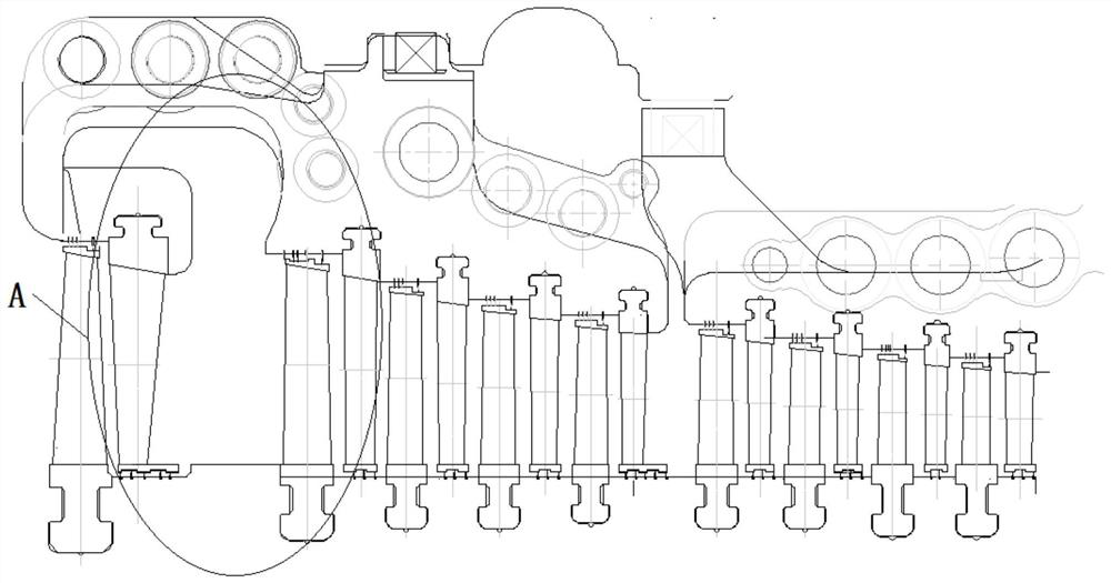
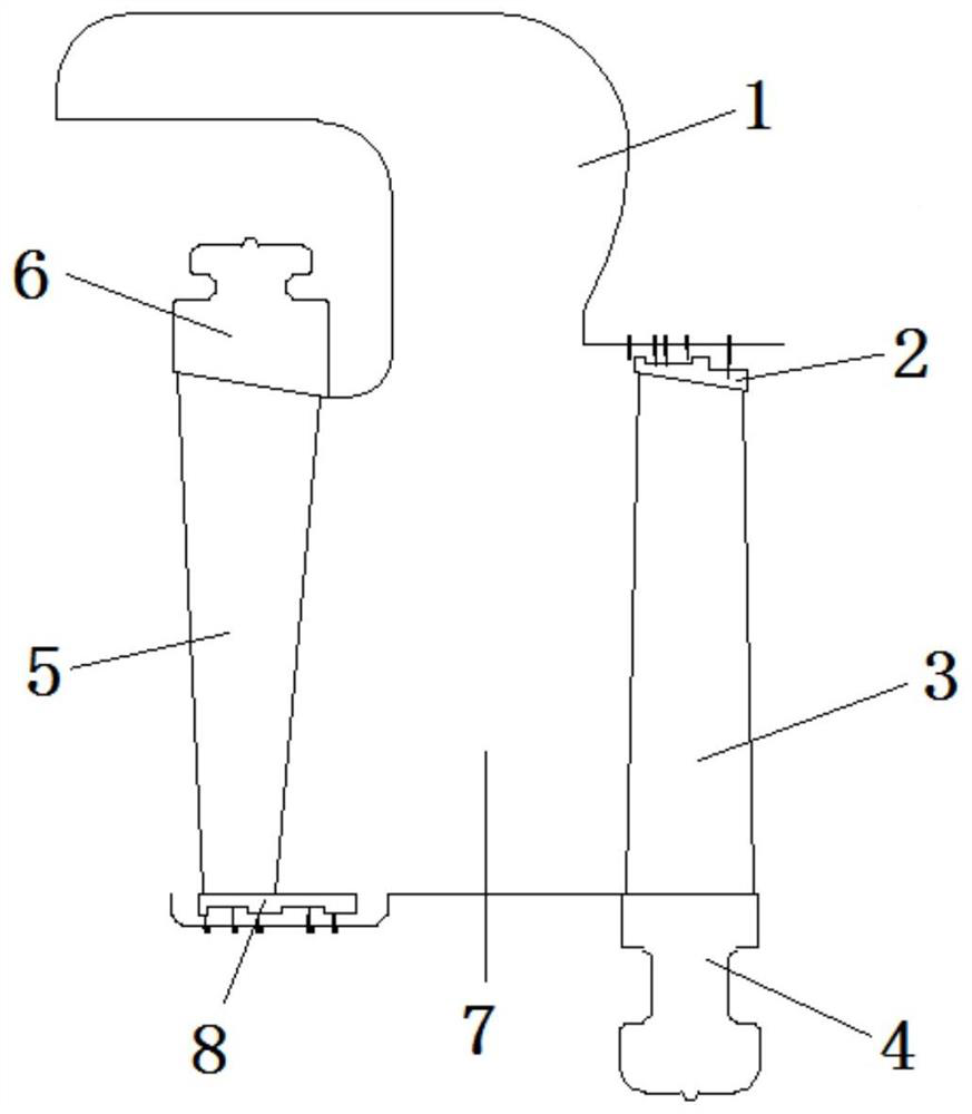
[0016] Specific implementation mode one: combine Figure 1-Figure 4 Describe this embodiment, the flow structure of a steam turbine medium-pressure steam extraction port described in this embodiment, it includes the front moving vane 3 of the steam extraction port and the rear stator vane 5 of the steam extraction port, the front moving vane 3 of the steam extraction port and the extraction port The static vane 5 behind the steam port is relatively installed in the medium-pressure steam extraction port of the steam turbine. The chamber between the moving vane 3 before the steam extraction port and the stationary vane 5 after the steam extraction port forms a moving vane flow chamber 7, and the moving vane 7 before the steam extraction port The steam extraction chamber 1 is formed between the vane 3 and the upper part of the stationary vane 5 after the steam extraction port and the middle pressure cylinder of the steam turbine, and the steam outlet turning of the steam extractio...

specific Embodiment approach 2

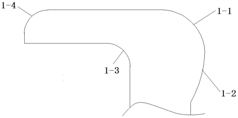
[0017] Specific implementation mode two: combination image 3 Describe this embodiment, the flow structure of a medium-pressure steam extraction port of a steam turbine described in this embodiment, the steam extraction chamber 1 is an integral part, the steam extraction chamber 1 is cast and easy to process, the The outer ring at the steam outlet corner is processed with a first arc 1-1 and a second arc 1-2, and the second arc 1-2 and the first arc 1-1 are sequentially connected along the air outlet direction, and the steam extraction chamber The inner ring of the steam outlet turning point of the chamber 1 is processed with a third arc 1-3, and the others are the same as in the first embodiment.

specific Embodiment approach 3

[0018] Specific implementation mode three: combination image 3 Describe this embodiment, the flow structure of a steam turbine medium-pressure extraction port described in this embodiment, the radius of the first arc 1-1 is 65mm, the radius of the second arc 1-2 is 170mm, and the third circle The radius of arc 1-3 is 35mm, the cavity height at the steam extraction outlet of extraction chamber 1 is 50mm, the cavity width at the extraction inlet of extraction chamber 1 is 90mm, and the diameter of each arc is All are obtained through multiple calculations, in line with the real flow of steam, which not only improves the flow efficiency of the medium pressure cylinder, but also greatly reduces the steam flow loss in the extraction chamber 1 from the perspective of aerodynamic economy. It can better guarantee the use of steam for the small machine after the four-extraction steam extraction, so that the owner can generate more economic benefits, and the others are the same as the ...


PUM


Abstract

The invention relates to a through-flow structure of a medium-pressure steam extraction opening of a steam turbine, in particular to a through-flow structure of a second medium-pressure steam extraction opening of a steam turbine, and aims to solve the problems that the through-flow efficiency before and after the steam extraction opening is reduced due to large steam extraction capacity of the medium-pressure second steam extraction opening of the steam turbine , and the energy loss of a steam extraction chamber is large, so that the output of a small steam turbine is not enough, and the economic benefit is influenced. A steam extraction opening front movable blade and a steam extraction opening rear static blade are oppositely installed in the medium-pressure steam extraction opening of the steam turbine ; a movable and static blade through-flow cavity is formed between the steam extraction opening front movable blade and the steam extraction opening rear static blade; a steam extraction cavity is formed between the steam extraction opening front movable blade and the steam extraction opening rear static blade and a steam turbine medium-pressure cylinder body; the steam outlet turning position of the steam extraction cavity is in an arc shape; the axial width of the movable and static blade through-flow cavity is 140 mm; the blade height of the steam extraction opening rear static blade is consistent with the blade height of the previous-stage steam extraction opening rear static blade; and the blade height of the steam extraction opening rear static blade is 1-5 mm shorter than the blade height of the steam extraction opening front movable blade. The device is used for extracting part of steam which does work in the steam turbine.

Description

technical field [0001] The invention relates to a flow structure of an intermediate-pressure steam extraction port of a steam turbine, in particular to a flow structure of a second medium-pressure steam extraction port of a steam turbine. Background technique [0002] High-power steam turbines are usually equipped with multiple steam extraction ports, the purpose of which is to improve the thermal efficiency and economy of the unit, and to extract part of the steam that has done work from the steam turbine to heat condensed water, feed water, and supply deaerators and civilian use. heating. Normally, the second steam extraction port of the medium pressure is the fourth-stage steam extraction, which is used to supply steam for small machines. Because of the large amount of steam extraction, it will have a severe impact on the flow before and after the steam extraction port, resulting in the exhaustion of the steam turbine. The flow efficiency before and after the steam port ...

Claims


Application Information

Patent Timeline
Patent Type & Authority Applications(China)
IPC IPC(8): F01D9/02F01D9/04
CPCF01D9/02F01D9/041
Inventor 赵洪羽李宇峰王丽华刘云锋王健潘春雨刘瑶徐林峰张峰阁张玥
Owner HARBIN TURBINE
Why Eureka
Try Eureka