Punching die for producing hard alloy saw-tooth tool bit

A technology of cemented carbide and stamping dies, which is applied in the field of stamping dies and stamping dies for the production of cemented carbide sawtooth cutter heads. It can solve the problems of affecting the quality of product processing, unstable fixing of the lower punch, and unstable operation of the mold. Achieve the effects of simple structure, saving maintenance cost and convenient disassembly

Inactive Publication Date: 2011-11-23
昆山长鹰硬质材料科技股份有限公司
View PDF5 Cites 2 Cited by
  • Summary
  • Abstract
  • Description
  • Claims
  • Application Information

AI Technical Summary

Problems solved by technology

[0002] The existing cutter head mold for the production of cemented carbide sawtooth cutter head, which uses the upper and lower punches of the press to stamp up and down at the same time to produce the cemented carbide sawtooth cutter head. Stability affects the quality of product processing, and the production efficiency is very low, which can easily cause damage to the lower punch and increase maintenance costs

Method used


Image

  • Punching die for producing hard alloy saw-tooth tool bit
  • Punching die for producing hard alloy saw-tooth tool bit

Examples


Embodiment

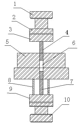
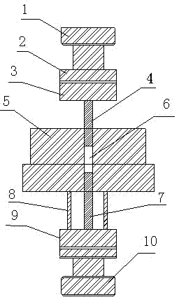
[0012] see figure 1 , the present embodiment is a stamping die for producing cemented carbide sawtooth cutter heads, including a die body 5, an upper punch seat 1, a lower punch seat 10, and upper and lower punches respectively installed on the upper and lower punch seats . Between the upper punch seat 1 and the upper punch 2 and between the lower punch seat 10 and the lower punch 7 are respectively provided with an upper fixed piece 3 and a lower fixed piece 9, and the upper fixed piece 3 is sleeved with an upper punch 4 , The lower punch 7 is sleeved on the lower fixing piece 10 .

[0013] The two sides of the lower punch 7 are also sleeved with ring pads 8 , and the ring pads 8 are placed on the upper end surface of the lower fixing piece 9 . The mold body 5 is placed on the upper end surface of the annular spacer 8 , the upper end surface of the lower punch 7 and the mold body 5 form a mold cavity 6 , and the upper punch 2 is correspondingly arranged above the mold cavit...


PUM


Abstract

The invention relates to a punching die for producing a hard alloy saw-tooth tool bit, comprising a die body, an upper punch seat, a lower punch seat, an upper punch and a lower punch, wherein the upper punch and the lower punch are respectively installed on the upper punch seat and the lower punch seat, an upper fixing sheet and a lower fixing sheet are respectively arranged between the upper punch seat and the upper punch as well as between the lower punch seat and the lower punch; the upper punch is sleeved on the upper fixing sheet; the lower punch is sleeved on the lower fixing sheet; annular pad forks are also sleeved at two sides of the lower punch; the die body is placed on the upper end faces of the annular pad forks; a die cavity is formed by the upper end face of the lower punch and the die body; and the upper punch is correspondingly arranged above the die cavity. Because the annular pad forks, the upper fixing sheet and the lower fixing sheet are arranged, the punching die for producing the hard alloy saw-tooth tool bit has simple structure and is convenient for mounting and dismounting; when the punching die is produced, the damage to the lower punch, caused by stress concentrated on the lower punch, is avoided by means of the annular pad forks through stamping the upper punch and the lower punch in one step, and the stamping is stable, therefore, the production efficiency is greatly improved, the maintenance cost is saved, and the product quality is enhanced.

Description

technical field [0001] The invention relates to a stamping die, in particular to a stamping die for producing cemented carbide sawtooth cutter heads, and belongs to the technical field of mechanical tool manufacturing. Background technique [0002] The existing cutter head mold for the production of cemented carbide sawtooth cutter head, which uses the upper and lower punches of the press to stamp up and down at the same time to produce the cemented carbide sawtooth cutter head. Stability affects the quality of product processing, and the production efficiency is very low, which can easily cause damage to the lower punch and increase maintenance costs. Contents of the invention [0003] In order to overcome the deficiencies of the prior art, the object of the present invention is to provide a stamping die for producing cemented carbide sawtooth cutter heads with stable stamping, simple structure, and convenient operation and disassembly. [0004] The present invention is ...

Claims


Application Information

Patent Timeline
Patent Type & Authority Applications(China)
IPC IPC(8): B21D37/10
Inventor 黄启君谢志勇张预分
Owner 昆山长鹰硬质材料科技股份有限公司
Why Eureka
Try Eureka