Welding fixture for thin-wall part

A technology for welding fixtures and thin-walled parts, which is applied in welding equipment, welding accessories, manufacturing tools, etc., can solve the problems that the contour of the welded parts cannot be corrected, it is difficult to ensure the welding quality, and cannot meet the production requirements, etc., and achieve argon flow Continuous, simple structure, and the effect of improving welding quality

Active Publication Date: 2011-11-23
SICHUAN FST MACHINING MFG
View PDF5 Cites 30 Cited by
  • Summary
  • Abstract
  • Description
  • Claims
  • Application Information

AI Technical Summary

Problems solved by technology

The disadvantage of the assembly positioning welding method is that the positioning is not accurate, resulting in low welding accuracy; the disadvantage of the pneumatic welding method is that the transmission force is small, and the contour of the welded parts cannot be corrected, so it cannot meet the production requirements.
Large thin-walled parts have thin walls and large diameters (the wall thickness is generally 1.5-3mm, and the diameter is greater than 800mm), so they are easy to deform. Even in a free state, the ellipticity of circular parts is very large (usually 5-10mm), It is even more difficult to guarantee the welding quality without special welding fixtures

Method used


Image

  • Welding fixture for thin-wall part
  • Welding fixture for thin-wall part
  • Welding fixture for thin-wall part

Examples


Embodiment Construction

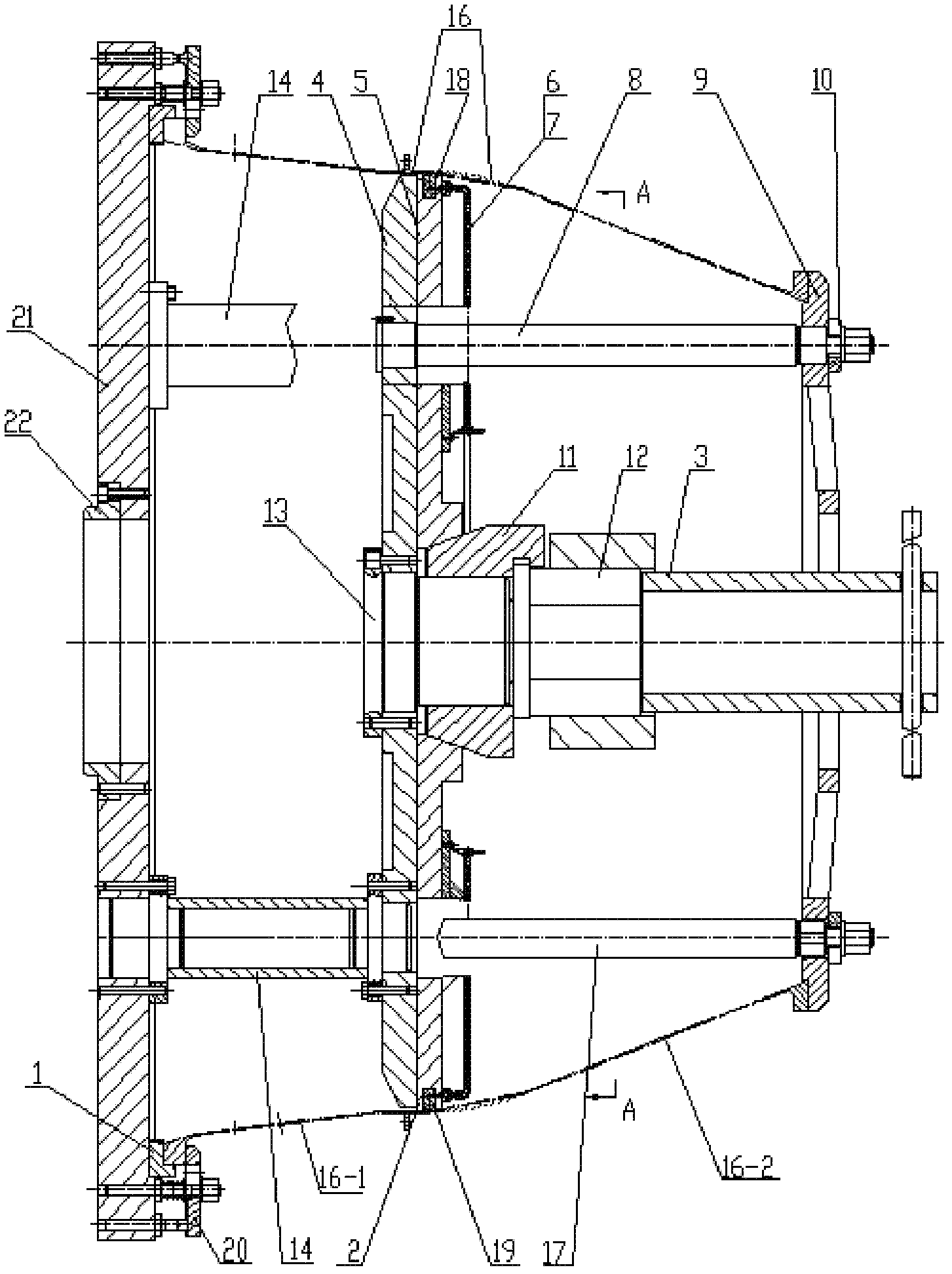
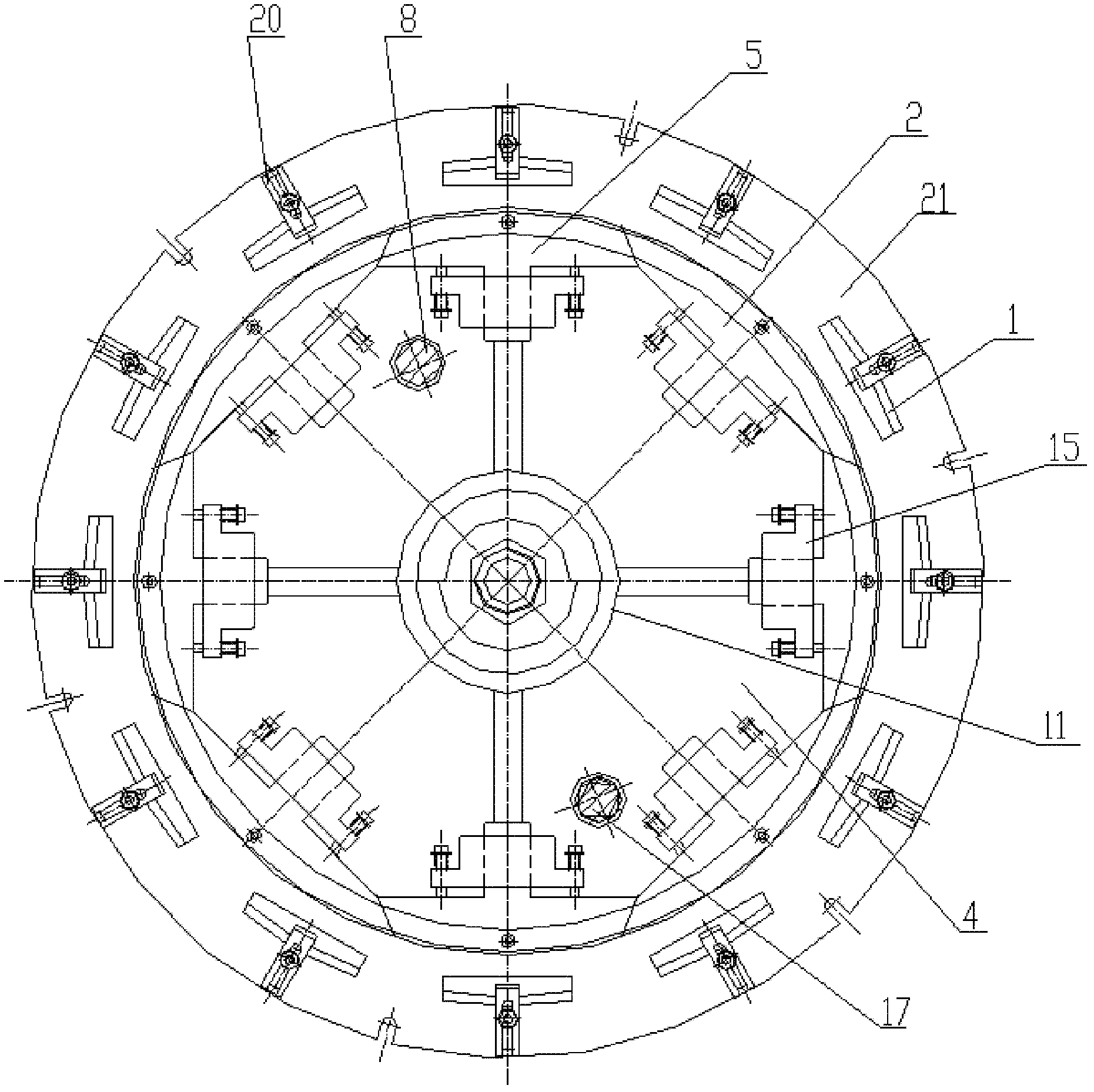
[0027] The structure and use of the welding jig for thin-walled parts according to the present invention will be further described below in conjunction with the accompanying drawings.

[0028] In this embodiment, the structure of the welding fixture used for thin-walled parts is as follows figure 1 , figure 2 As shown, it includes base 21, supporting plate 4, pressing plate 9, mandrel 22, positioning block 1, pressing block 20, positioning shaft 13, wedge block 11, force transmission nut 12, wrench 3, driving part 5, driven part 2 , the first insert 18, the second insert 19 and the guide 15.

[0029] The base 21 is in the shape of a truncated cone, the support plate 4 is a circular plate, the pressure plate 9 is provided with a circular positioning boss matching the size of the inner surface of the welded part, and the base 21 is connected by four connecting shafts 14 Connected with the support plate 4, the four connecting shafts are distributed on the same circumference, a...


PUM

PropertyMeasurementUnit
thicknessaaaaaaaaaa
diameteraaaaaaaaaa

Abstract

The invention relates to a welding fixture for a thin-wall part. In the welding fixture for the thin-wall part, a pedestal is connected with a supporting plate through a connecting shaft; a pressing plate is used for fixing the welded part; a mandrel is fixed in a central hole of the pedestal; the number of positioning blocks is at least four; each positioning block is arranged on the same circumference of the pedestal; the number of pressing blocks is as same as that of the positioning blocks; the pressing blocks are used for fixing the welded part; one end of a positioning shaft is fixed inthe central hole of the supporting plate; a wedge block is arranged on the positioning shaft; a dowel nut is arranged at the thread section of the positioning shaft and is connected with the wedge block; the number of driving parts is at least three; the number of driven parts is as same as that of the driving parts; the number of guide parts is equal to the sum of the number of the driving partsand the driven parts; each driving part and each driven part are placed on the supporting plate along the circumference of the supporting plate at intervals; each guide part corresponding to one driving part or one driven part is fixed on the supporting plate; a first insert is arranged on one driving part; a second insert is arranged on one driven part; and an air tap jack and a vent hole communicated with the air tap jack are formed on each insert.

Description

technical field [0001] The invention belongs to a welding fixture, in particular to a welding fixture used for end-to-face argon arc welding of two large thin-walled parts. Background technique [0002] Argon arc welding is an arc welding method that uses argon gas as a protective medium. During the argon arc welding process, argon gas must be continuously fed into the welding position to protect the weld seam and ensure welding quality. [0003] It is understood that there is no special fixture for the existing argon arc welding, and the assembly positioning welding method and pneumatic method are usually used for welding. The disadvantage of the assembly positioning welding method is that the positioning is not accurate, resulting in low welding accuracy; the disadvantage of the pneumatic welding method is that the transmission force is small, and the contour of the welded parts cannot be corrected, so it cannot meet the production requirements. Large thin-walled parts ha...

Claims


Application Information

Patent Timeline
Patent Type & Authority Applications(China)
IPC IPC(8): B23K9/32B23K9/16
Inventor 刘建乔惠芳周海峰姜宝华陈栋权杨莉玫罗仁俊
Owner SICHUAN FST MACHINING MFG
Why Eureka
Try Eureka