Supercharge Your Innovation With Domain-Expert AI Agents!

High-efficiency energy-saving technology for bullet train

A high-efficiency, energy-saving, motor-car technology, applied in the direction of air resistance reduction technology, railway car body, railway car body parts, etc., can solve the problems of changing into power, no resistance, and large wasted power.

Inactive Publication Date: 2011-11-23
李仕清
View PDF5 Cites 0 Cited by
  • Summary
  • Abstract
  • Description
  • Claims
  • Application Information

AI Technical Summary

Problems solved by technology

[0002] At present, the front end or top resistance surface of the high-speed train running on various railways adopts ordinary plane or curved surface. This kind of structure has high resistance and has no function of changing resistance into power. Or the wasted power is very large. When various high-speed trains and bullet trains move at high speed, the resistance generated by the air flow field becomes a large factor of power consumption. According to the current dynamic principle, it can no longer meet the needs of ultra-high speed movement. When the moving object has a single structure, the resistance wave it receives becomes a resistance body with the most perfect structure and the strongest resistance, so the resistance it receives is also the largest. Only by breaking the structure of the resistance body, by changing the structure of the resistance wave or the force body , that is, by changing the force on the front end or top of the front of the car, the resistance can be effectively reduced and the fuel consumption can be reduced

Method used


Image

  • High-efficiency energy-saving technology for bullet train
  • High-efficiency energy-saving technology for bullet train

Examples


Embodiment approach 1

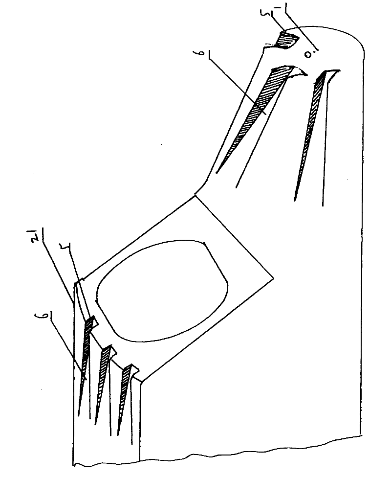
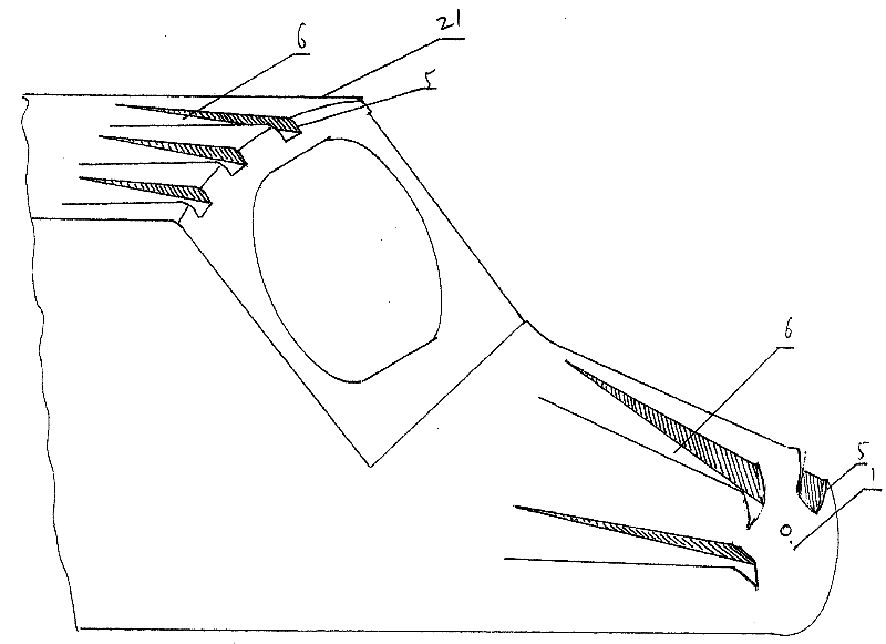
[0023] A high-efficiency energy-saving technology for motor vehicles, such as figure 1 As shown, the high-efficiency and energy-saving technology for motor cars in the first embodiment of the present invention includes a motor car head 1 and a car body 2. The motor car head 1 and the car body 2 are connected or formed as one. The mouth 5 extends backward or is distributed on the car body 2 in a shape of opening and gradually enlarged to form a turbulent flow groove 6, and two side walls 3 are formed in the turbulent flow groove 6, and at least one turbulent flow notch is arranged on the roof 9 7. Extending backward or distributing on the vehicle body 2 with openings gradually enlarged backward to form at least one turbulent groove 8 .

[0024] According to the above-mentioned structure, since there is a turbulent notch 5 on the head 1 of the power-assisted motor car, compared with the conventional motor car, the turbulent notch 5 has the function of decomposing the resistance...


PUM


Abstract

The invention provides a high-efficiency energy-saving technology for a bullet train. The high-efficiency energy-saving technology for the bullet train has small resistance and large thrust force, and is technologically characterized in that: the front end resistance surfaces of various express trains, bullet trains and the like are provided with turbulent current recesses, or turbulent current grooves are formed by extending backwards from the turbulent current recesses. The high-efficiency energy-saving technology is characterized in that: the resistance surfaces of the front ends of train heads or train bodies of various express trains and bullet trains are provided with at least one turbulent current recess which is opened upwards; 1, at least one turbulent current groove is formed on the front end resistance surface in an extending manner; 2, at least one turbulent current groove is formed on the front end resistance surface in gradually magnifying manner; 3, at least one step-shaped turbulent current groove is formed on the front end resistance surface in a stepwise extending manner; 4, at least one step-shaped turbulent current groove is formed on the front end resistance surface in a stepwise gradually magnifying manner; and 5, the bottom of the turbulent current groove or the step-shape turbulent current groove is provided with carinate wings which project along the central line of the turbulent current groove close to the center of the recess and incline downwards at two sides.

Description

Technical field: [0001] The invention relates to a high-efficiency locomotive boosting technology, which is used on the front end or top resistance surface of the locomotive of high-speed trains running on various railways. Background technique: [0002] At present, the front end or top resistance surface of the high-speed train running on various railways adopts ordinary plane or curved surface. This kind of structure has high resistance and has no function of changing resistance into power. Or the wasted power is very large. When various high-speed trains and bullet trains move at high speed, the resistance generated by the air flow field becomes a large factor of power consumption. According to the current dynamic principle, it can no longer meet the needs of ultra-high speed movement. When the moving object has a single structure, the resistance wave it receives becomes a resistance body with the most perfect structure and the strongest resistance, so the resistance it r...

Claims


Application Information

Patent Timeline
Patent Type & Authority Applications(China)
IPC IPC(8): B61D17/02
CPCY02T30/32Y02T30/00
Inventor 李仕清
Owner 李仕清
Features
  • R&D
  • Intellectual Property
  • Life Sciences
  • Materials
  • Tech Scout
  • Unparalleled Data Quality
  • Higher Quality Content
  • 60% Fewer Hallucinations
Learn More