Gripping device

A technology of equipment and guide grooves, applied in the direction of conveyor objects, load hanging components, transportation and packaging, etc., can solve problems such as bracket deformation

Active Publication Date: 2011-11-23
KRONES AG
View PDF4 Cites 8 Cited by
  • Summary
  • Abstract
  • Description
  • Claims
  • Application Information

AI Technical Summary

Problems solved by technology

If the gripper arm is placed accidentally and at high speed on a rigid base or on an inflexible object,

Method used


Image

  • Gripping device
  • Gripping device
  • Gripping device

Examples


Embodiment Construction

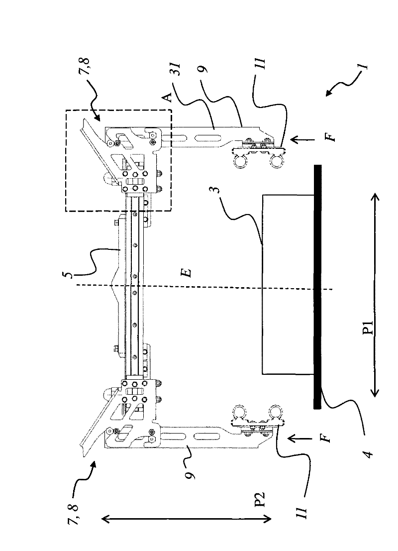
[0026] figure 1 The schematic diagram of FIG. 1 shows an embodiment of the gripping device 1 . The gripping device 1 comprises two gripping arms 9 which are horizontally spaced apart from each other and are arranged on the support 5 via a mechanical connection 7 . The gripping arms 9 can be moved relative to each other in the direction of the arrow P1 preferably with a synchronous advancing movement or by synchronous moving away from each other, which is achieved by a suitable level in the top region of the gripping device 1 or in the support 5 Boot device to make sure. Furthermore, the entire top section or support 5 is movable in the vertical direction P2 together with the gripping arm 9 guided and held thereon. In the embodiment shown, the movement in the vertical direction is not carried out by movement of the gripping arm 9 . The movement in the vertical direction P2 is instead brought about by lifting and / or lowering the support 5 and thus the gripping arm 9 arranged ...


PUM


Abstract

Disclosed is a gripping device (1) which is applied to at least one object (3), particularly for packaging goods. The gripping device is provided with two gripping arms (9) which are parallelly spaced and are arranged on a support (5) via a mechanical connection mechanism (7). The gripping arms (9) are opposite to each other and can move in the vertical direction (P2). The gripping arms (9) can be loosened at the support (5) via the mechanical connection mechanism (7) under the effect of a specified force (F) in the vertical direction and facing toward the support (5).

Description

technical field [0001] The invention relates to a gripping device for receiving and / or handling at least one object according to the preamble of claim 1 . Furthermore, the invention relates to a method with the features of the independent method claim 12 for releasing a gripping arm from a support in the event of a collision of the gripping arm with a rigid surface or an object. Background technique [0002] Different gripping devices have been known in the prior art. For example, DE 102 04 513 A1 discloses a gripping device with two gripping arms for gripping objects. One of the two gripping arms can be attached to the transport. The other gripping arm is used to open and close the gripping device with an actuator. If the gripper arm is placed accidentally and at high speed on a rigid base or an inflexible object, the forces occurring here can cause deformations of the gripper arm and / or the support of the gripper arm. Contents of the invention [0003] A priority tas...

Claims


Application Information

Patent Timeline
IPC IPC(8): B66C1/44B65G47/90
CPCB65G47/905
Inventor 克劳斯·埃滕胡贝尔伯恩德·科尔弗洛里安·赫特尔
Owner KRONES AG
Why Eureka
Try Eureka