Bridge erection machine aided support leg structure

A technology for auxiliary outriggers and bridge erecting machines, which is applied in the direction of erecting/assembling bridges, bridges, bridge construction, etc., which can solve problems such as inconvenient installation, low safety factor, and difficult processing, and achieve high flexibility, easy installation, and processing The effect of simple process

Inactive Publication Date: 2011-11-23
无锡澳玛高铁科技有限公司
View PDF0 Cites 2 Cited by
  • Summary
  • Abstract
  • Description
  • Claims
  • Application Information

AI Technical Summary

Problems solved by technology

In order to ensure the safe and stable passage of the bridge, the bridge erecting machine needs the assistance of outriggers when passing the hole. The expansion joints of the outriggers of the traditional auxiliary bridge erecting machine are square expansion joints. Obviously, this kind of outrigger structure is adopted. There are disadvantages that the height of the outriggers is not easy to adjust; the processing is difficult, the installation is inconvenient and the safety factor is low

Method used


Image

  • Bridge erection machine aided support leg structure
  • Bridge erection machine aided support leg structure
  • Bridge erection machine aided support leg structure

Examples


Embodiment Construction

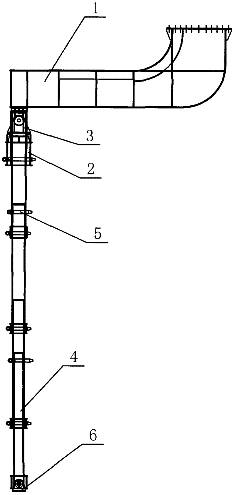
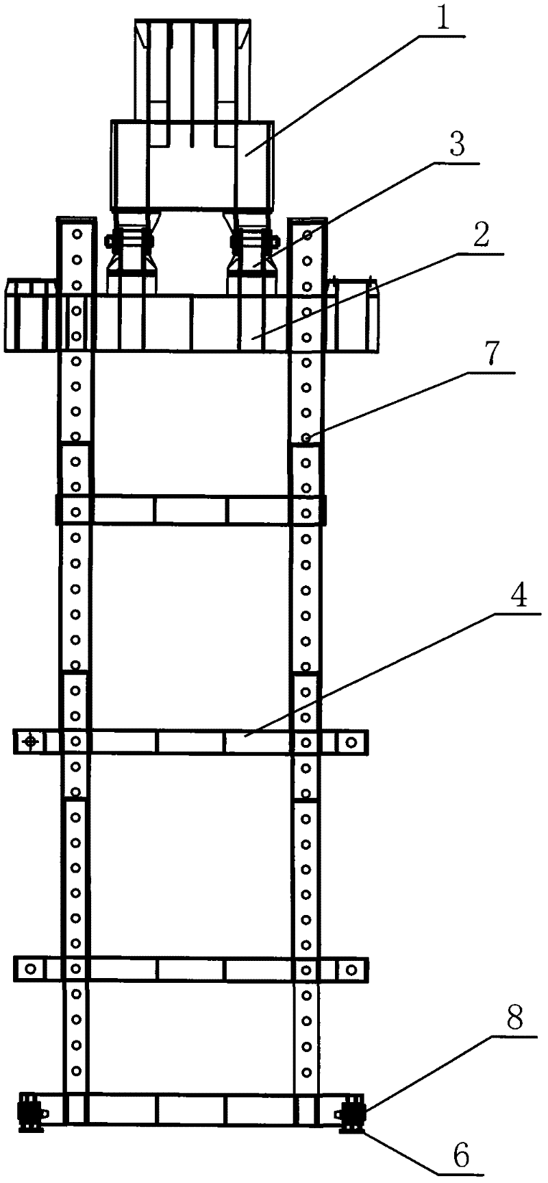
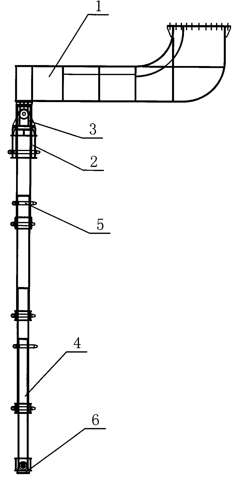
[0013] Please refer to figure 1 and figure 2 as shown, figure 1 It is a structural schematic diagram of the auxiliary leg structure of the bridge erecting machine of the present invention; figure 2 It is a cross-sectional view of the auxiliary leg structure of the bridge erecting machine of the present invention.

[0014] In this embodiment, the auxiliary outrigger structure of the bridge erecting machine is composed of four telescopic joints 4 suitably spliced ​​together. The telescopic joints 4 are circular tube structures, and several height adjustment holes are opened on the surface of the circular tubes. 7. The height adjustment hole 7 is provided with a pin 5, the pin 5 passes through the height adjustment hole 7 corresponding to two adjacent expansion joints 4 to connect the two expansion joints 4, and the auxiliary leg structure of the bridge erecting machine One end is hinged on the support 6 through the support steel pin 8, and the other end is provided with an ...


PUM


Abstract

The invention discloses a bridge erection machine aided support leg structure. One end of the bridge erection machine aided support leg structure is hinged on a trunk beam of a bridge erection machine through an upper cross beam, and the other end of the bridge erection machine aided support leg structure is hinged on a support through a support steel pin; the bridge erection machine aided support leg structure consists of a plurality of telescopic joints by sleeving and splicing; the telescopic joints are in round tube structures, the surfaces of the round tubes are provided with a plurality of height adjusting holes, bolts are arranged to match the height adjusting holes, and the bolts pass through the corresponding height adjusting holes of the two adjacent telescopic joints to connect the two telescopic joints. Because the telescopic joints of the bridge erection machine aided support leg structure are in round tube structures and the adjacent telescopic joints are connected through the bolts and the height adjusting holes, compared with the traditional support leg structure, the bridge erection machine aided support leg structure has the advantages that: the structure is easily installed, the machining process is simple, and the height of the support leg can be adjusted flexibly, safely and reliably.

Description

technical field [0001] The invention relates to a device for assisting a bridge-erecting machine to pass through a hole, in particular to an auxiliary leg structure of a bridge-erecting machine. Background technique [0002] At present, the bridge erecting machine has become an indispensable engineering equipment for erecting highway bridges, conventional railway bridges, and passenger-only railway bridges. The bridge erecting machine is a device that places prefabricated girders on prefabricated bridge piers. Its main functions are The beams are lifted, transported into position and lowered. However, the bridge erecting machine is very different from the crane in the general sense. It requires harsh conditions, and there is walking on the beam, or longitudinal movement. In order to ensure the safe and stable passage of the bridge, the bridge erecting machine needs the assistance of outriggers when passing the hole. The expansion joints of the outriggers of the traditional ...

Claims


Application Information

Patent Timeline
Patent Type & Authority Applications(China)
IPC IPC(8): E01D21/00
Inventor 王飞
Owner 无锡澳玛高铁科技有限公司
Why Eureka
Try Eureka