Dynamic compaction machine and arm rack device thereof

A technology of dynamic tamping machine and jib, which is applied in the fields of soil protection, construction, and infrastructure engineering, etc. It can solve the problems of reducing the 4' effective working height of the rammer, difficulty in fully utilizing the space, and low working efficiency of the dynamic tamping machine. , to avoid motion interference, increase safety, and improve work efficiency

Inactive Publication Date: 2011-11-23
BEIJING CSR TIMES LOCOMOTIVE & ROLLING STOCK MECHANICS
View PDF6 Cites 16 Cited by
  • Summary
  • Abstract
  • Description
  • Claims
  • Application Information

AI Technical Summary

Problems solved by technology

[0007] Please refer again figure 1 In the prior art, the fixed pulley 6' connected to the rammer 4' is directly installed on the upper section arm 1', so that the horizontal distance between the installed rammer 4' and the support arm is relatively short, and the rammer 4' is in the It is easy to interfere with the movement of the support arm during the ascent process, and the space under the arm is not easy to be fully utilized, especially when the diameter of the rammer 4' is relatively large (about 2.2 to 3.0m), in order to avoid the rammer 4' collided with the supporting arm frame, the lifting height of the rammer 4' dropped significantly, which reduced the effective working height of the rammer 4', and the corresponding working efficiency of the dynamic compaction machine was relatively low

Method used


Image

  • Dynamic compaction machine and arm rack device thereof
  • Dynamic compaction machine and arm rack device thereof
  • Dynamic compaction machine and arm rack device thereof

Examples


Embodiment Construction

[0030] The core purpose of the present invention is to provide an arm support device of a dynamic compaction machine, which can effectively improve the working efficiency of the dynamic compaction machine. In addition, another core of the present invention is to provide a dynamic compaction machine including the above-mentioned boom device.

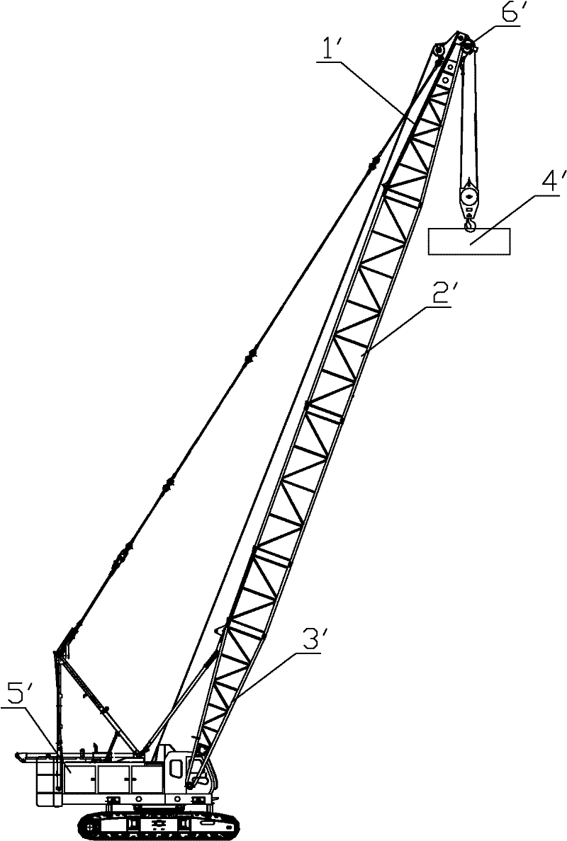
[0031] Without loss of generality, the present invention takes the boom device installed on a dynamic compaction machine with the car body of a crawler crane as the chassis as an example. It should be understood that the boom device of the present invention can also be arranged on other types of car bodies middle.

[0032] In order to enable those skilled in the art to better understand the technical solutions of the present invention, the present invention will be further described in detail below in conjunction with the accompanying drawings and specific embodiments.

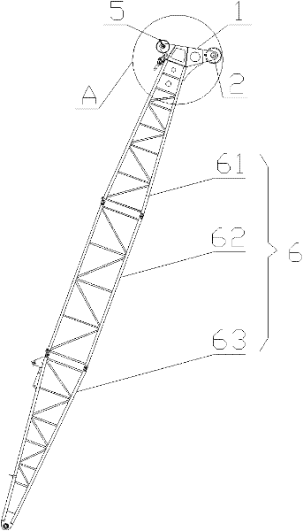
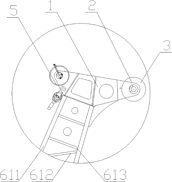
[0033] Please refer to figure 2 and image 3 , figure 2 It is ...


PUM


Abstract

The invention discloses an arm rack device of a dynamic compaction machine. The arm rack device comprises a supporting arm rack (6), the bottom of which is connected with the body of the dynamic compaction machine; the arm rack device also comprises a front stretching arm head device (1) arranged at the top of the supporting arm rack (6), and a fixed pulley (2) for lifting a rammer (7) of the dynamic compaction machine is arranged at the front end of the front stretching arm head device (1); the rammer (7) is relatively far from the supporting arm rack (6), so the operating space of the rammer (7) in the horizontal direction is enlarged, movement interference between the rammer (7) and the supporting arm rack (6) is avoided, and the operating safety is increased; and the rammer (7) of the same diameter can be lifted to a greater height, so that the operating performance of the dynamic compaction machine is fully exerted, and the work efficiency of the dynamic compaction machine is improved. Moreover, the invention also provides the dynamic compaction machine comprising the arm rack device.

Description

technical field [0001] The invention relates to the technical field of dynamic ramming machines, in particular to an arm support device of a dynamic ramming machine. In addition, the present invention also relates to a dynamic compaction machine comprising the above-mentioned boom device. Background technique [0002] The dynamic tamping machine is a mechanical equipment used for ground and foundation compaction in engineering construction. It mainly uses the strong impact force generated by the falling of the rammer to improve the strength of the foundation, anti-seismic ability, and eliminate the collapsibility of the ground. [0003] Please refer to the attached figure 1 , figure 1 It is a structural schematic diagram of a typical dynamic compaction machine in the prior art. [0004] The structure of a typical dynamic compaction machine in the prior art mainly includes a control system, a lifting mechanism, and compacting equipment connected with the lifting mechanism,...

Claims


Application Information

Patent Timeline
Patent Type & Authority Applications(China)
IPC IPC(8): E02D3/046
Inventor 韩侠刘长胜牟宗月黄志文董树云刘桂然
Owner BEIJING CSR TIMES LOCOMOTIVE & ROLLING STOCK MECHANICS
Why Eureka
Try Eureka