Clutch Driving Device

A driving device and clutch technology, applied to clutches, mechanical drive clutches, mechanical equipment, etc., can solve problems such as increasing energy consumption

Inactive Publication Date: 2011-11-23
HYUNDAI MOTOR CO LTD
View PDF8 Cites 4 Cited by
  • Summary
  • Abstract
  • Description
  • Claims
  • Application Information

AI Technical Summary

Problems solved by technology

[0025] Specifically, in lever type 1 as described above, since the stroke from the pivot point B to the point of action C is directly proportional to the stroke of the actuator 500, it is necessarily difficult to control by precisely controlling the stro...

Method used


Image

  • Clutch Driving Device
  • Clutch Driving Device
  • Clutch Driving Device

Examples


Embodiment Construction

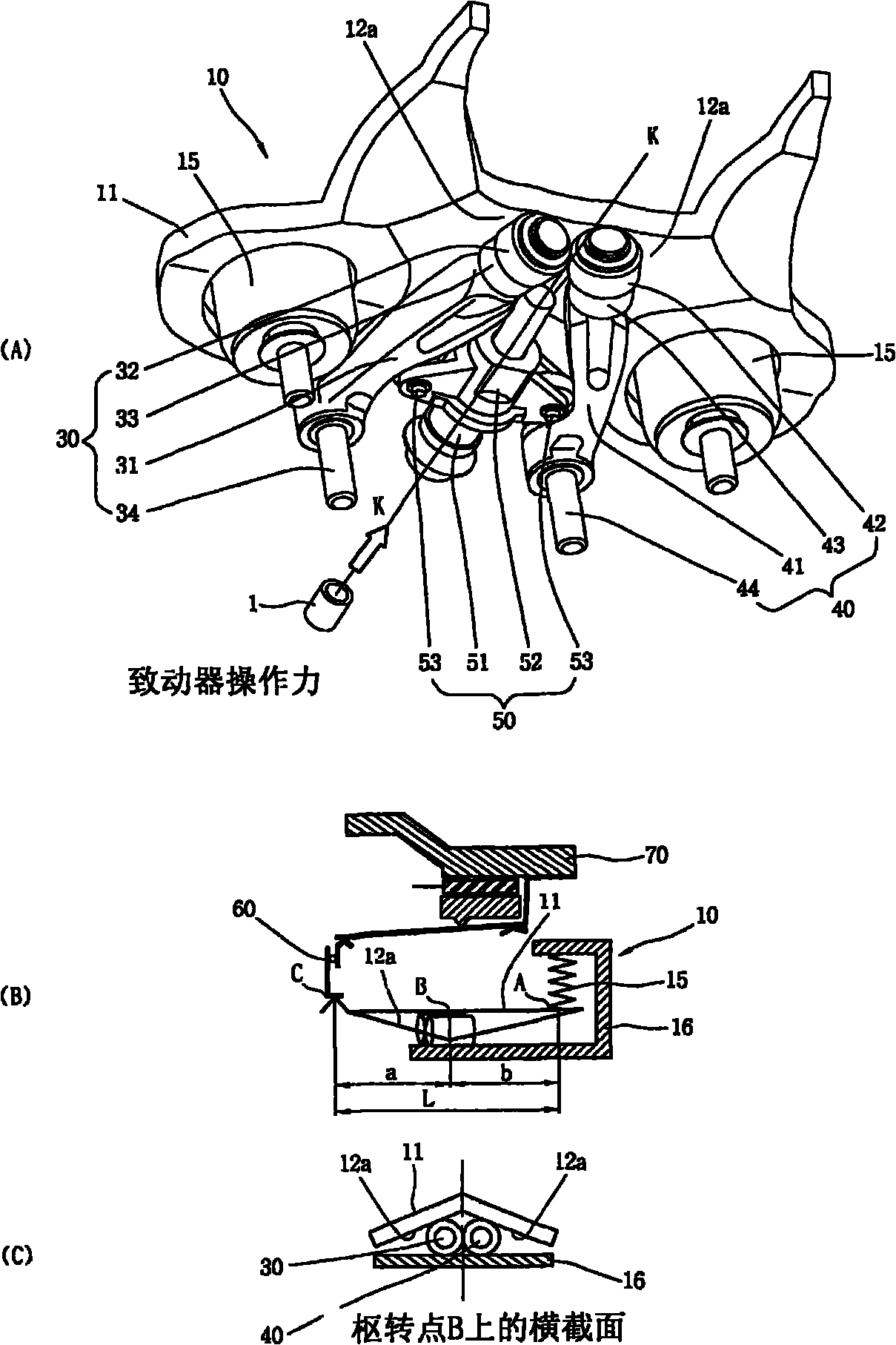
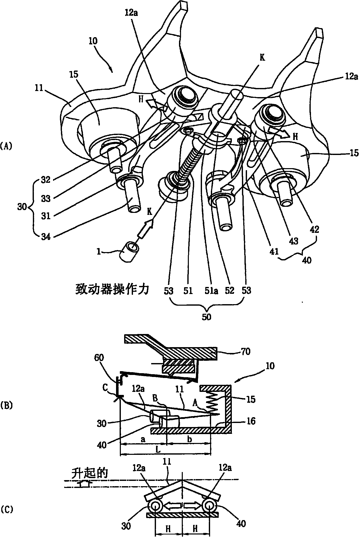
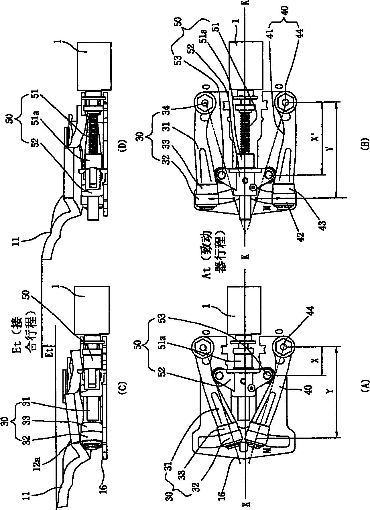
[0043] Such as figure 1 As shown, the clutch driving device includes an actuator 1 and an energy supply unit, the actuator 1 generates rotational power, and when the energy supply unit engages the clutch 70 by generating a stroke to the release bearing 60, the actuator 1 At the same time, the energy supply unit moves left and right relative to the two sides from the axial centerline K-K of the actuator 1 while converting the rotation into linear motion.

[0044] Although a motor is used as the actuator 1, an actuator utilizing hydraulic pressure or air pressure may also be used.

[0045] The clutch drive according to the invention is called a horizontal movement and vertical translation clutch drive (HVCDD), which is based on an energy supply unit arranged horizontally with respect to the axial centerline K-K of the actuator 1 side-to-side motion, and converts the horizontal motion into a squeezing force that squeezes the clutch by creating a vertical translation.

[0046] ...


PUM


Abstract

A clutch driving device includes a pair of first and second roller wing arms horizontally moving to both sides by moving body moving forward/backward on an axial center line of an actuator and a roller inclined cam surface defining a move path of a pivot is formed such that first and second roller wing arms horizontally move to both sides from the axial center line of actuator, on the surface of a lever generating a stroke at a release bearing. Therefore, the lever can be lifted above a clutch engagement gap where a sufficient stroke is generated at the release bearing engaging a clutch, such that it is possible to achieve sufficient performance even if the output of actuator is reduced by the amount of energy consumption which is relative reduced.

Description

[0001] Cross References to Related Applications [0002] This application claims priority from Korean Patent Application No. 10-2010-0045935 filed May 17, 2010, the entire contents of which are hereby incorporated by reference for all purposes. technical field [0003] The present invention relates to a clutch driving device, in particular to a clutch driving device which generates a lever-side vertical translation via a moving distance of a roller to operate the clutch in a horizontal movement and vertical translation method, said roller moving horizontally to Both sides and convert vertical translation to operational translation for squeezing release bearings. Background technique [0004] In general, when a manual transmission is operating, the engine power is temporarily cut off before the shift gear is engaged, and then the engine power is transmitted after the shift gear is engaged, and the clutch is used for this operation. [0005] The clutch is generally operated u...

Claims


Application Information

Patent Timeline
IPC IPC(8): F16D23/12
CPCF16D23/12F16D2023/123F16D2023/126
Inventor 金锺烨赵诚庸张贤德
Owner HYUNDAI MOTOR CO LTD
Why Eureka
Try Eureka