
Rivet nut electric tool

A technology of electric tools and rivet nuts, which is applied in the field of machinery, can solve the problems of unstable torsion spring torsion, prone to failure, large idle stroke, etc., and achieve the effects of strong motor gears, precise stroke control, and powerful power

Active Publication Date: 2015-01-28
洪劲松
View PDF5 Cites 14 Cited by
  • Summary
  • Abstract
  • Description
  • Claims
  • Application Information

AI Technical Summary

Problems solved by technology

[0004] (1) Since the mechanical clutch stroke cannot be adjusted, the clutch requirement can only be met at a fixed position, and the empty stroke is large, resulting in waste of time and power consumption, and low production efficiency;
[0005] (2) Relying on the torsion force of the mechanical torsion spring to ensure the size of the rotation force, the tightening force of the rivet nut is small when it is installed and loosened, and the rivet nut cannot be unscrewed when encountering an abnormality, and when the torsion spring is used frequently, it will repeatedly Due to friction and impact, the torsion spring is easy to get hot, which will cause the torsion force of the torsion spring to become unstable with the change of temperature, resulting in the hidden danger of damage or incomplete screwing of the rivet nut during the loading process;
[0006] (3) The normal operation is extremely cumbersome. It is necessary to adjust multiple threaded structural parts at the same time to ensure the screw-in length and riveting length. , the thread needs to be tightened (if the thread is not tightened, it is easy to loosen and change, which will cause the stroke to change and damage the thread). Often the adjusted stroke changes after the thread is tightened. It is difficult for non-professionals and unskilled people to operate smoothly. When using rivet nuts in batches, the adjustment time is often longer than the use time;
[0007] (4) The structure is complex, there are many parts, and it is prone to failure;
[0008] (5) The power of the motor is small, relying on the interference fit between the outer diameter of the motor shaft and the inner diameter of the motor teeth, the fastening force is small, and it is easy to slip and loosen, which limits the pulling force and cannot rivet larger-sized rivet nuts;
[0009] (6) The service life is low, and many parts are vulnerable parts, and it is not easy to replace

Method used


Image

  • Rivet nut electric tool
  • Rivet nut electric tool
  • Rivet nut electric tool

Examples


Embodiment 1

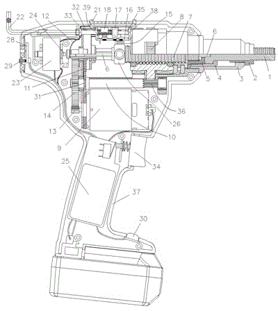
[0044] Such as figure 1 , Figure 4 and Figure 5 As shown, the rivet nut electric tool includes an outer cover 37, a pull rod 1, a gun head 2, an outer sleeve 3, a pull rod fixing lock nut 4, a screw lock nut 5, a hexagonal connecting rod 6, a gear transmission system, and a stroke Control system, screw nut assembly and clutch control system;

[0045] Described gear transmission system comprises motor 9, motor gear 13 and gear assembly, and described gear assembly comprises gear I14, gear II31 and connecting shaft 10, and connecting shaft 10 is provided with gear I14 and gear II31 successively from left to right, and connecting shaft The right end of 10 is processed with a hobbing gear 36, which can also be replaced by a gear at the right end of the connecting shaft 10; one end of the motor 9 is connected with the circuit board 25 fixed in the outer cover 37 through a control line, and the other end of the motor 9 is connected with a motor gear 13 ; The motor gear 13 is me...

Embodiment 2

[0057] Such as Figure 6 and Figure 7 As shown, the electromagnet control device includes a return spring II42, an electromagnet 23 and an electromagnet push rod 24; the return spring II42 is arranged between the gear I14 of the gear assembly and the positioning rear cover 33, and the left side of the gear I14 is arranged There is an electromagnet 23, and the right side of the electromagnet 23 is provided with an electromagnet push rod 24; the gear II31 of the gear assembly is arranged on the right side of the meshing gear of the gear clutch assembly 11; the hexagonal connecting rod 6 is fixedly connected with the right end of the shaft of the gear clutch assembly 11 . After the electromagnet 23 is energized, the electromagnet push rod 24 pushes the gear assembly to separate the meshing teeth of the gear II and the gear clutch assembly 11, and the hobbing teeth 36 on the connecting shaft 10 mesh with the meshing teeth on the screw nut 8 to perform riveting; When the electro...

Embodiment 3

[0059] Such as Figure 8 and Figure 9As shown, the electromagnet control device includes back-moving spring 141, spring collar 40, electromagnet 23 and electromagnet push rod 24; Hexagonal structure, the right end of the shaft is processed with a connecting hole for connecting with the hexagonal connecting rod 6, the left end of the hexagonal connecting rod 6 is provided with a groove, and a spring collar 40 is fixed in the groove, and the return spring I41 is set on the hexagonal connecting rod 6 , one end is connected with the spring collar 40, and the other end is fixed on the stepped hole in the screw mandrel 7. The connection part processed at the front end of the shaft of the gear clutch assembly 11 is generally arranged in a hexagonal structure, which is used to connect with the connection hole processed at the left end of the hexagonal connecting rod 6, and the connecting hole is correspondingly arranged as a hexagonal hole. Under the action of the electromagnetic f...


PUM


Abstract

The invention relates to a rivet nut electric tool, which is used in the technical field of machinery. The rivet nut electric tool comprises an outer cover, a clutch control system, a gear transmission system, a stroke control system and a screw rod screw nut assembly, wherein the clutch control system, the gear transmission system, the stroke control system and the screw rod screw nut assembly are arranged in the outer cover, the clutch control system is matched with the gear transmission system for performing separation and reunion and transmission, the stroke control system precisely controls the stroke, when the screw rod moves, signals can be provided, screw nut riveting can be carried out, a gear clutch assembly drives a hexagonal connecting rod for completing rivet nut screwing-in and screwing-out operation, three sensors are connected with a circuit board through control wires, the clutch control system is matched with the three sensors to work, and a trigger is arranged on the outer cover. The rivet nut electric tool has the advantages that the power is high, rivet nuts in different specifications can be riveted, the circuit board precisely controls the clutch control system, the gear transmission system and the stroke control system, the rivet nuts can be enabled to be reliably installed in place for riveting, in addition, the stroke and the electric quantity are visible, the operation is convenient, and high practicability is realized.

Description

technical field [0001] The invention belongs to the technical field of machinery, in particular to electric tools for rivet nuts. Background technique [0002] The rivet nut tool is a tool specially used for the installation of rivet nuts, including pneumatic rivet nut guns and electric rivet nut guns. The pneumatic rivet nut tool has the advantages of fast speed and large pulling force. The rotating blades of the air motors are frequently used or have a slightly dusty working environment, they will suddenly get stuck and not work, there is a great hidden danger of the motor crashing, and the air motor has a small torque due to the volume limit, although the riveting tension It can be made larger, but the volume will also increase; while the electric rivet nut gun can be said to screw in and out the rivet nut mechanism, it can be said that it will not crash, the torque is large, and the size is small, so it is widely used, but due to the electric The rivet nut gun has the f...

Claims


Application Information

Patent Timeline
IPC IPC(8): B25B21/00B25B23/00
CPCB25B21/00B25F5/001B21J15/048B21J15/24B25B27/0014
Inventor 洪劲松
Owner 洪劲松
Learn More