Tool magazine of machine tool

a technology of machine tools and tool magazines, which is applied in the field of tool magazines of machine tools, can solve the problems of deteriorating productivity, increasing tool change time and non-machining time, and reducing productivity, so as to reduce the change time and maximize productivity, the effect of quick change of tools

Pending Publication Date: 2022-04-07
DN SOLUTIONS CO LTD
View PDF0 Cites 1 Cited by
  • Summary
  • Abstract
  • Description
  • Claims
  • Application Information

AI Technical Summary

Benefits of technology

[0036]According to the tool magazine of the machine tool according to the present disclosure, the magazine unit is installed on the saddle, and the gripper part clamps the tool while avoiding the flange portion of the tool so that the tool accommodated in the gripper part of the magazine unit is loaded or unloaded in the direction perpendicular to the tool axis at the time of changing the tools, by the tool changing part movably installed on the saddle and the tool changing part transfer part configured to move the tool changing part independently of the column. With the structure in which the gripping part of the change arm directly grips the flange portion of the tool, the tool changing part may quickly change the tools between the spindle and the gripper part of the magazine unit simply by be rectilinearly reciprocated by the tool changing part transfer part. Therefore, it is possible to reduce the tool change time and maximize the productivity.
[0037]In addition, it is possible to quickly change the tools, minimize the movement time for changing the tools in the medium-sized or large-sized machine tool having a long length in the width direction, automatically change the tools, and maximize the user's convenience.
[0038]Moreover, the tool magazine of the machine tool according to the present disclosure may reduce the likelihood of interference or collision by minimizing the movement distance required to change the tools, thereby improving the stability and reliability of the machine tool.
[0039]Moreover, according to the tool magazine of the machine tool according to the present disclosure, the respective constituent components including the magazine unit and the tool changing part may be small in size, and the entire machine tool may be small in size and light in weight, such that the spatial utilization may be maximized, and the maintenance and manufacturing costs are reduced.
[0040]Furthermore, according to the tool magazine of the machine tool according to the present disclosure, the tool changing part only rectilinearly reciprocates and rotates, and the spindle performs an inherent function of moving upward and downward in the height direction to change the tools. Therefore, the tool changing part may be small in size, and the tool changing part may quickly move, thereby reducing the non-machining time, reducing vibration and noise generated while the machine tool moves, increasing the lifespan of the machine tool, and maximizing the machining precision.

Problems solved by technology

In order to change the tools, the spindle, which performs the machining operations at various positions, needs to move to the fixed magazine and the fixed ATC to change the tools and then return to the machining positions, which causes problems of an increase in tool change time and non-machining time and a deterioration in productivity.
In addition, these problems are worse in a machine tool in the related art, particularly, a medium-sized or large-sized machine tool in which a stroke in a width direction (X-axis direction) is 2 m or more.
That is, in the case in which the stroke in the width direction is as large as 2 m or more, the spindle needs to reciprocate in a long section to the magazine and the ATC fixed to the lateral surface of the machine tool to change the tools, which causes a problem of the risk of interference and collision with the workpiece.
A separate configuration for the upward or downward movement needs to be provided, which complicates the configuration of the ATC, increases a size of the ATC, and finally increases a size of the machine tool.
Moreover, the machine tool in the related art increases in size to reduce the risk of interference and collision, which causes problems of deterioration in spatial utilization, inconvenience caused by the heavy machine tool, and an increase in costs required to manufacture and maintain the machine tool.
Furthermore, in the case of the machine tool in the related art, the ATC needs to not only rotate, but also move upward and downward with respect to the spindle in order to change the tools, which causes problems of increases in size of the ATC, weight of the machine tool, and manufacturing costs.

Method used


Image

  • Tool magazine of machine tool
  • Tool magazine of machine tool
  • Tool magazine of machine tool

Examples


Embodiment Construction

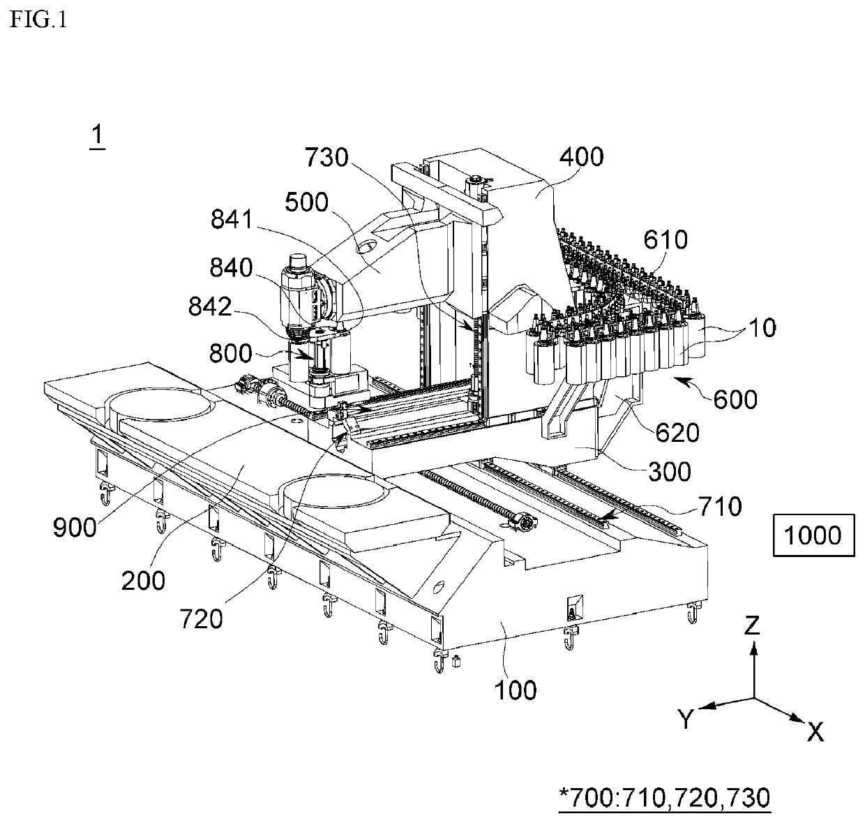
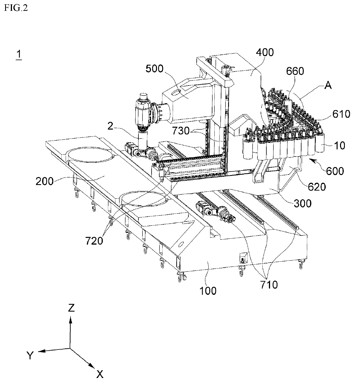
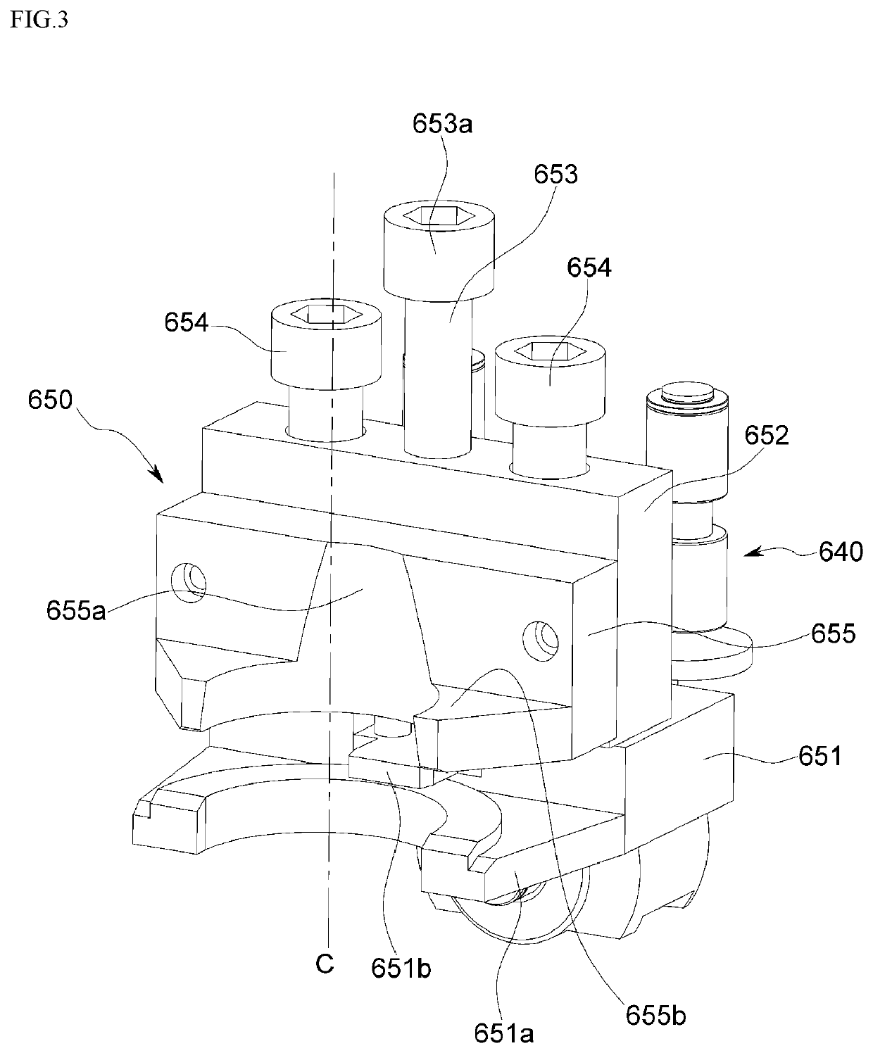
[0080]Hereinafter, a tool magazine for a machine tool according to an exemplary embodiment of the present disclosure will be described in detail with reference to the drawings. The following exemplary embodiments are provided as examples for fully transferring the spirit of the present disclosure to those skilled in the art. Therefore, the present disclosure is not limited to the exemplary embodiments described below and may be specified as other aspects. Further, in the drawings, a size and a thickness of the apparatus may be exaggerated for convenience. Like reference numerals indicate like constituent elements throughout the specification.

[0081]Advantages and features of the present disclosure and methods of achieving the advantages and features will be clear with reference to exemplary embodiments described in detail below together with the accompanying drawings. However, the present disclosure is not limited to the exemplary embodiments disclosed herein but will be implemented ...


PUM


Abstract

The present disclosure relates to a tool magazine of a machine tool such as a moving column-type machining center, in which a magazine unit is installed on a saddle, a tool accommodated in a gripper part of the magazine unit is loaded or unloaded in a direction perpendicular to a tool axis, and a gripping part of a change arm directly grips a flange portion of the tool at the time of changing the tools by means of a tool changing part movably installed on the saddle and a tool changing part transfer part configured to move the tool changing part independently of a column, thereby reducing tool change time, improving productivity, minimizing a collision or mechanical interference, and improving stability and reliability in the medium-sized or large-sized machine tool having a length in a width direction.

Description

FIELD OF THE DISCLOSURE[0001]The present disclosure relates to a tool magazine of a machine tool, and more particularly, to a tool magazine of a machine tool such as a moving column-type machining center, in which a magazine unit is installed on a saddle, and a tool accommodated in a gripper part of the magazine unit is loaded or unloaded in a direction perpendicular to a tool axis at the time of changing the tools by means of a tool changing part movably installed on the saddle and a tool changing part transfer part configured to move the tool changing part independently of a column, thereby reducing tool change time and improving productivity.BACKGROUND OF THE DISCLOSURE[0002]In general, a machine tool refers to a machine used to process metal / non-metal workpieces in a desired shape and dimension using a suitable tool by using various types of cutting or non-cutting methods.[0003]Various types of machine tools including a turning center, a vertical / horizontal machining center, a d...

Claims


Application Information

Patent Timeline
Patent Type & Authority Applications(United States)
IPC IPC(8): B23Q3/155
CPCB23Q3/15526B23Q3/15513B23Q1/626B23Q3/15724B23Q3/15766B23Q3/15713B23Q2003/155418B23Q2003/155428B23Q2003/155446B23Q3/16
Inventor JEONG, SEONGHOON
Owner DN SOLUTIONS CO LTD
Why Eureka
Try Eureka