Eureka AIR delivers breakthrough ideas for toughest innovation challenges, trusted by R&D personnel around the world.

Light-emitting diode (LED) street lamp

A technology of LED street lamps and lamps, which is applied in the cooling/heating devices of lighting devices, outdoor lighting, sustainable buildings, etc. It can solve the problems of increased light loss, aging and yellowing of lamps, failure to meet the requirements of road lighting, etc., and achieve improvement Uniformity of illuminance and the effect of improving brightness

Inactive Publication Date: 2011-11-23
吴建平
View PDF8 Cites 0 Cited by
  • Summary
  • Abstract
  • Description
  • Claims
  • Application Information

AI Technical Summary

Problems solved by technology

[0003] (1) Use a single LED point light source. The light distribution structure of this point light source must pass the secondary light distribution. A filter is used on each point light source to control the direction of light. The lamp will affect the design of the light distribution structure of the lamp. 10%~15% light loss due to the light source with the filter, and the filter is made of plastic, which will age and turn yellow when used in a high temperature environment for a long time, which will gradually increase the light loss of the lamp;
[0004] (2) Use a small-volume high-power integrated light source. There is a high-power integrated light source installed in the optical cavity of this street lamp. In order to expand the irradiation area of ​​the light emitted by the light source, a concave-convex mirror is added. This lamp has no scientific design. The light distribution structure design cannot meet the requirements of road lighting

Method used


Image

  • Light-emitting diode (LED) street lamp
  • Light-emitting diode (LED) street lamp
  • Light-emitting diode (LED) street lamp

Examples


Embodiment Construction

[0019] The present invention will be described in detail below in conjunction with the accompanying drawings and embodiments.

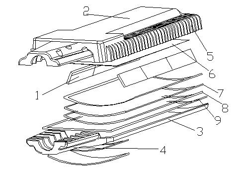
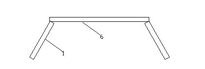
[0020] Such as figure 1 and figure 2 As shown, an LED street lamp includes an optical cavity with an LED high-power integrated light source 1. The optical cavity is formed by a lamp body upper cover 2 and a lamp body lower cover 3. The lamp body upper cover 2 and the lamp body lower cover Between the cover 3, the tempered glass 8, the first silicone ring 7 between the lamp body upper cover 2 and the tempered glass 8, and the second silicone ring 9 between the lamp body lower cover 3 and the tempered glass 8 are used as a sealing structure to the optical cavity. For sealing, it also includes a power cavity 4 that provides electric energy for the LED high-power integrated light source 1 , and a heat dissipation device 5 .

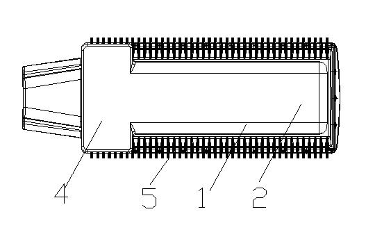
[0021] image 3 for figure 1 and image 3 The cross-sectional view of the structure in the optical cavity can better see the ...


PUM


Abstract

The invention relates to a light-emitting diode (LED) street lamp, which comprises an optical cavity with two LED high-power integrated light sources, a power cavity which supplies electric energy to the LED high-power integrated light sources and a radiating device, wherein the optical cavity is formed by covering a lamp body upper cover on a lamp body lower cover; a sealing structure is arranged between the lamp body upper cover and the lamp body lower cover; the two LED high-power integrated light sources are symmetrically arranged on the left and right sides of the interior of the optical cavity by using a central axis relative to the vertical direction of the lamp body upper cover as a starting point and inclining lower edges of the LED high-power integrated light sources outwards by 5 to 45 DEG; and the two LED high-power integrated light sources form downward inner installation angles of 10 to 90 DEG. The LED street lamp has the advantages that: the two LED high-power integrated light sources which irradiate each other can be used for expanding a light irradiation range, so a dark area cannot be generated between two adjacent lamps, and illumination uniformity is improved; meanwhile, a reflector is arranged in the optical cavity, so the upward residual light of the light sources is completely reflected in a controllable range of irradiating points in the center of the lamp, and brightness can be improved.

Description

technical field [0001] The invention relates to an LED street lamp. Background technique [0002] The light distribution structure of existing LED street lamps mainly has the following two forms: [0003] (1) Use a single LED point light source. The light distribution structure of this point light source must pass the secondary light distribution. A filter is used on each point light source to control the direction of light. The lamp will affect the design of the light distribution structure of the lamp. 10%~15% light loss due to the light source with the filter, and the filter is made of plastic, which will age and turn yellow when used in a high temperature environment for a long time, which will gradually increase the light loss of the lamp; [0004] (2) Use a small-volume high-power integrated light source. There is a high-power integrated light source installed in the optical cavity of this street lamp. In order to expand the irradiation area of ​​the light emitted by ...

Claims


Application Information

Patent Timeline
Patent Type & Authority Applications(China)
IPC IPC(8): F21S8/00F21V19/00F21V29/00F21W131/103F21Y101/02F21V29/503F21V29/70
CPCY02B20/72
Inventor 吴建平
Owner 吴建平
Why Eureka
Eureka Blog
Learn More