
Extension testing device

A test device and test piece technology, applied in the direction of applying stable tension/pressure to test the strength of materials, can solve the problems of low precision, insufficient power of the biaxial tensile testing machine, limited loading ratio, etc., and achieve a large test tension range. Effect

Active Publication Date: 2011-11-23
SHANGHAI JIAO TONG UNIV
View PDF6 Cites 18 Cited by
  • Summary
  • Abstract
  • Description
  • Claims
  • Application Information

AI Technical Summary

Problems solved by technology

[0011] In the prior art literature, the uniaxial tensile testing machine has a single function, and the biaxial tensile testing machine has disadvantages such as insufficient power, limited loading ratio and low precision.

Method used


Image

  • Extension testing device
  • Extension testing device
  • Extension testing device

Examples


Embodiment 1

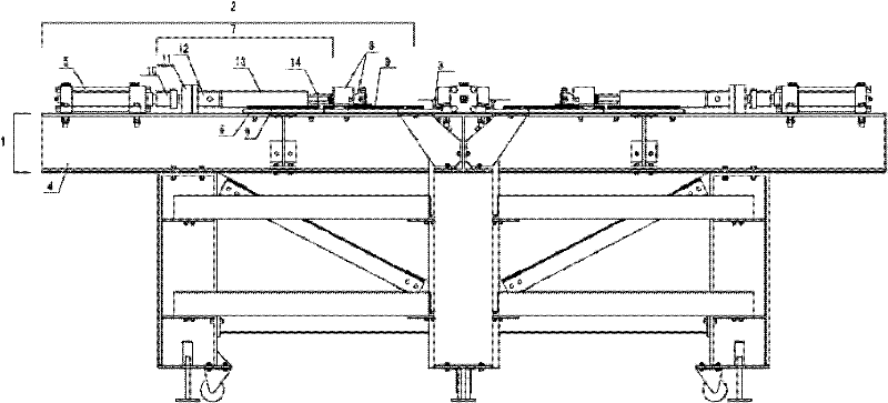
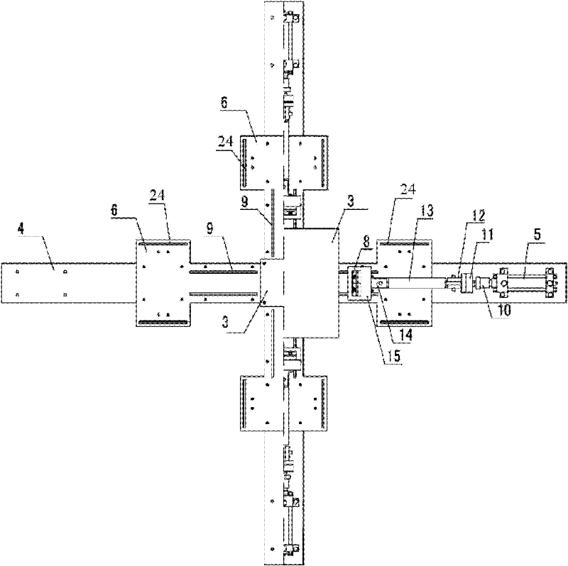
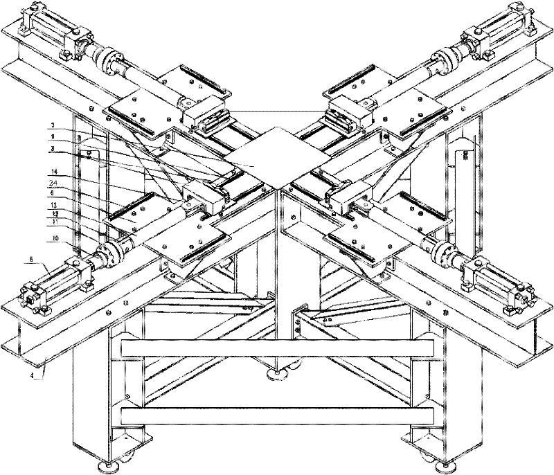
[0032] Such as figure 1 , figure 2 with image 3 As shown, this embodiment includes: a vehicle frame assembly 1, four sets of stretching mechanisms 2 and a specimen fixing assembly 3, wherein: the vehicle frame assembly 1 is fixedly connected to the four sets of tensioning mechanisms 2 and the specimen fixing assemblies 3 respectively.

[0033] The vehicle frame assembly 1 includes four sets of stands 4 distributed orthogonally, and the four sets of stands 4 are connected with the four sets of stretching mechanisms 2 in one-to-one correspondence.

[0034] The stretching mechanism 2 includes: an oil cylinder 5, a guide rail support plate 6, a tension conversion assembly 7, a clamping assembly 8 and a linear guide rail 9, wherein: the oil cylinder 5 is fixedly connected to the end of the stand 4, and the guide rail support plate 6 is connected to the stage The frame 4 is fixedly connected, the oil cylinder 5 is connected with the tension conversion assembly 7, the linear guid...


PUM


Abstract

The invention relates to an extension testing device in the technical fields of material mechanics experiments and building structure material tests. The extension testing device provided by the invention comprises a frame component, four groups of extension mechanisms and a specimen fixing component, wherein the frame component is respectively and fixedly connected with the four groups of extension mechanisms and the specimen fixing component. The extension testing device provided by the invention fully utilizes the characteristics of a cylinder, a clamping component and a linear guide rail, has the advantages of multiple test piece dimensions, multiple test functions and large test tension range and can be used for building film material tests and airship skin tests.

Description

technical field [0001] The invention relates to a device in the technical field of material mechanics experiment and building structure material test, in particular to a tensile test device. Background technique [0002] Polymer composite fabric film materials have the characteristics of light weight, high strength, chemical resistance, and durability, and are used in modern architectural structures, aerospace and other industrial fields, such as architectural membrane structures, aviation airships, aerospace parachutes or soft landing systems. Fabric film is generally composed of base cloth and coating. The base cloth is made of polymer materials and synthetic fibers are woven into cloth. In the field of construction, there are mainly polyester fibers, glass fibers, etc. In the field of aerospace, there are mainly polyester fibers, Aramid fiber, nylon fiber, etc., the coating mainly includes polytetrafluoroethylene and polytetrafluoroethylene, and the coating or lamination ...

Claims


Application Information

Patent Timeline
IPC IPC(8): G01N3/10
Inventor 陈务军施光林张丽何艳丽张大旭
Owner SHANGHAI JIAO TONG UNIV
Learn More