Device for testing tension of test piece

A tensile test and test piece technology, which is applied in the direction of applying stable tension/pressure to test the strength of materials, etc., can solve the problems of inconvenient use of optical measurement systems, complex structure of tensile testing machines, and large space occupation. Smooth process without vibration, light weight, small footprint effect

Active Publication Date: 2013-08-07
HARBIN INST OF TECH
View PDF5 Cites 10 Cited by
  • Summary
  • Abstract
  • Description
  • Claims
  • Application Information

AI Technical Summary

Problems solved by technology

[0003] The purpose of the present invention is to solve the existing problems of complex structure, large space occupation, high cost, inconvenient use with optical measurement system, and poor adaptability of the existing tensile testing machine, and further provide a method for testing specimens. device for stretch testing

Method used


Image

  • Device for testing tension of test piece
  • Device for testing tension of test piece
  • Device for testing tension of test piece

Examples


specific Embodiment approach 1

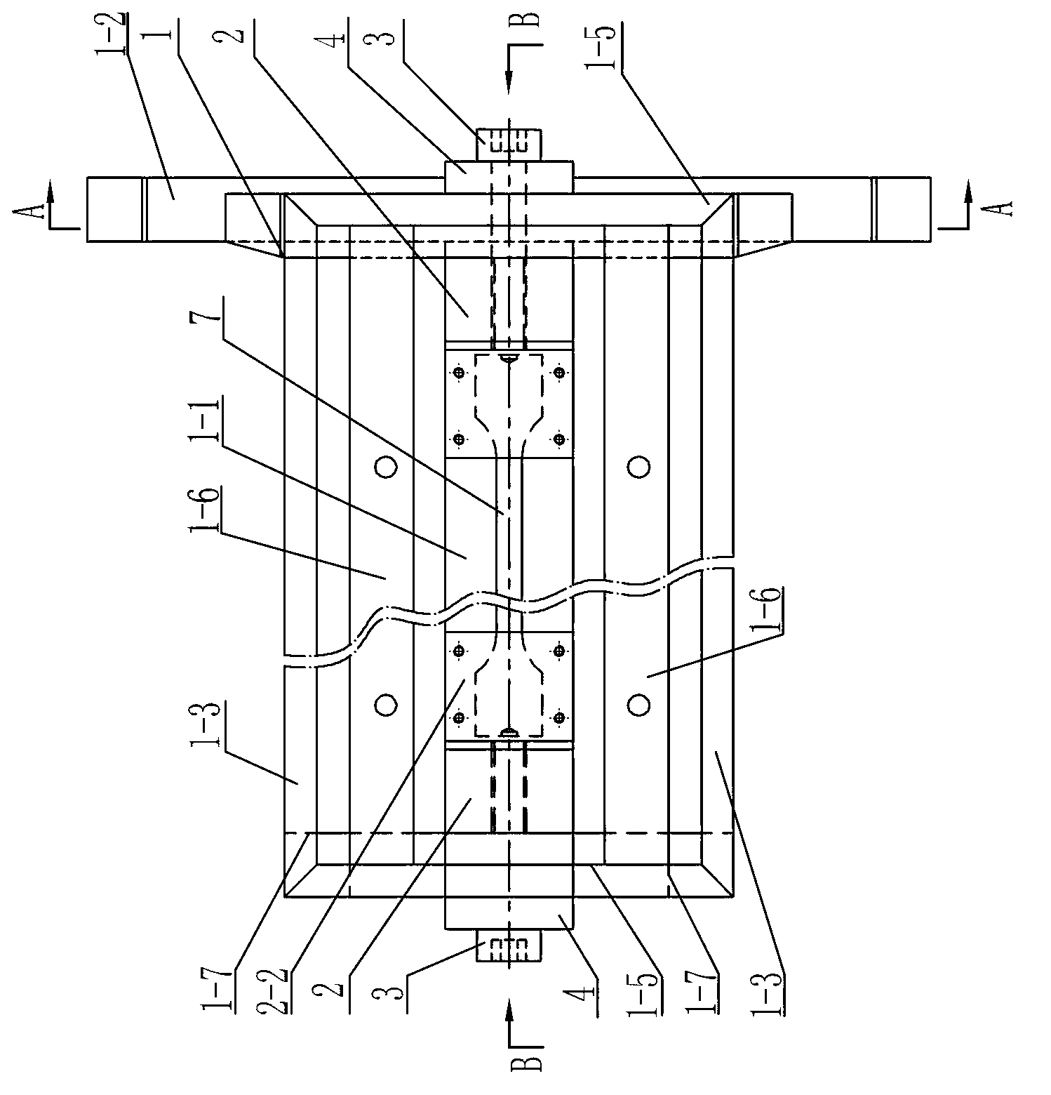
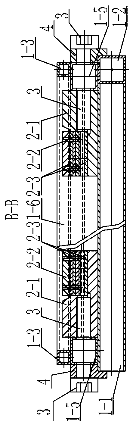
[0008] Specific implementation mode one: combine Figure 1 to Figure 10 To illustrate this embodiment, a device for tensile testing of specimens in this embodiment includes a base 1, two chuck assemblies 2, two pretensioners 3 and two top plates 4;

[0009] Each set of chuck assembly 2 includes a card seat 2-1, a cover plate 2-2 and a plurality of backing plates 2-3, the card seat 2-1 is provided with a groove 2-6, and the size of the groove 2-6 The shape is the same as the size and shape of the end of the test piece 7 to be stretched, and the side wall of the holder 2-1 is provided with a threaded hole 2-3 communicating with the groove 2-6, and the axial direction of the threaded hole 2-3 is Consistent with the length direction of the test piece to be stretched, the size and shape of the backing plate 2-3 are the same as the size and shape of the groove 2-6, and the backing plate 2-3 is placed in the groove 2-6 to support the test piece to be stretched. The piece 7 and the c...

specific Embodiment approach 2

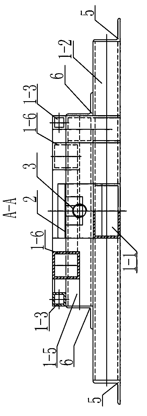
[0011] Specific implementation mode two: combination Figure 1 to Figure 6 To illustrate this embodiment, the base 1 in this embodiment includes a first square pipe 1-1, a second square pipe 1-2, a square frame 1-3, two third-party pipes 1-5, and two fourth square pipes 1-6. Two fifth square pipes 1-7, the second square pipe 1-2 are arranged horizontally, one of the third party pipes 1-5 is stacked on the second square pipe 1-2, and the length direction of the two is the same , two fifth square pipes 1-7 are vertically arranged side by side, another third-party pipe 1-5 is connected between the two fifth square pipes 1-7, two third-party pipes 1-5 are arranged side by side, two Two fourth square pipes 1-6 are arranged side by side between the first third-party pipes 1-5, and the length direction of the two fourth square pipes 1-6 is perpendicular to the length direction of the two third-party pipes 1-5. The first square pipe 1-1 connected to the other third party pipe 1-5 and...

specific Embodiment approach 3

[0012] Specific implementation mode three: combination Figure 1 to Figure 6 To illustrate this embodiment, the base 1 in this embodiment also includes two first angle steels 5 and two second angle steels 6, and the two ends of the second square pipe 1-2 are respectively connected with a first angle steel 5, wherein Two ends of a third-party pipe 1-5 are respectively connected with a second angle steel 6, and two second angle steels 6 are connected with the first square pipe 1-1. Such setting facilitates the fixing of the second square tube and the third party tube, increases the rigidity of the entire base, and prevents the specimen from bending or torsional deformation or lateral translation during the loading process. Others are the same as in the second embodiment.


PUM


Abstract

The invention discloses a device for testing tension of a test piece, and relates to a device used for the tension of the test piece. In order to solve the problems that the existing tension testing machine is complicated in structure, large in occupied area, high in cost, inconvenient to used in a manner of being matched with an optical measurement system, and poor in adaptability. The device for testing the tension of the test piece comprises a base, two sets of chuck components, two pretensioners and two top plates, wherein each set of chuck component comprises a chuck seat, a cover plate and a plurality of cushion plates; a groove is formed in the chuck seat; a threaded hole communicated with the groove is formed in the side wall of the chuck seat; the axial direction of the threaded hole is identical to the length direction of a test piece to be tensioned; the cover plate covers the upper surfaces of the cushion plates and is detachably connected with the chuck seat; the two top plates are arranged on the base in a face-to-face manner; the two sets of chuck seats are arranged on the base between the two top plates; the opening ends of the grooves in the side walls of the two sets of chuck seats are arranged in the face-to-face manner; and one end of each pretensioner is in threaded connection with the corresponding threaded hole. The device for testing the tension of the test piece is used in the fields of materials science, mechanics or optics.

Description

technical field [0001] The invention relates to a device for stretching a test piece, in particular to a device for applying a tensile load to a standard tensile test piece or used in conjunction with a laser interference device and an optical camera, which can be used for the tensile loading process A tensile loading device for measuring and analyzing the stress and strain state of the local area of ​​the test piece. Background technique [0002] Tensile testing is one of the most commonly used and important testing methods in the field of materials science. That is, the material to be studied is processed into a standard tensile sample, and the tensile test is carried out on the sample to obtain the elastic modulus E and yield strength σ of the material. b and tensile strength σ s important mechanical parameters of the material. Tensile tests are usually performed on large tensile testing machines. However, if it is necessary to obtain the stress-strain distribution an...

Claims


Application Information

Patent Timeline
IPC IPC(8): G01N3/08
Inventor 刘雪松潘海博闫忠杰尚哲王为董志波方洪渊
Owner HARBIN INST OF TECH
Why Eureka
Try Eureka