Film loading device

A loading device and film technology, applied in the direction of applying stable tension/pressure to test the strength of materials, can solve the problems of high precision and large displacement loading, avoid high cost and improve measurement accuracy , the effect of simple structure

Inactive Publication Date: 2013-06-19
TSINGHUA UNIV
View PDF4 Cites 9 Cited by
  • Summary
  • Abstract
  • Description
  • Claims
  • Application Information

AI Technical Summary

Problems solved by technology

However, none of them can well solve the contradict...

Method used


Image

  • Film loading device
  • Film loading device
  • Film loading device

Examples


Embodiment 1

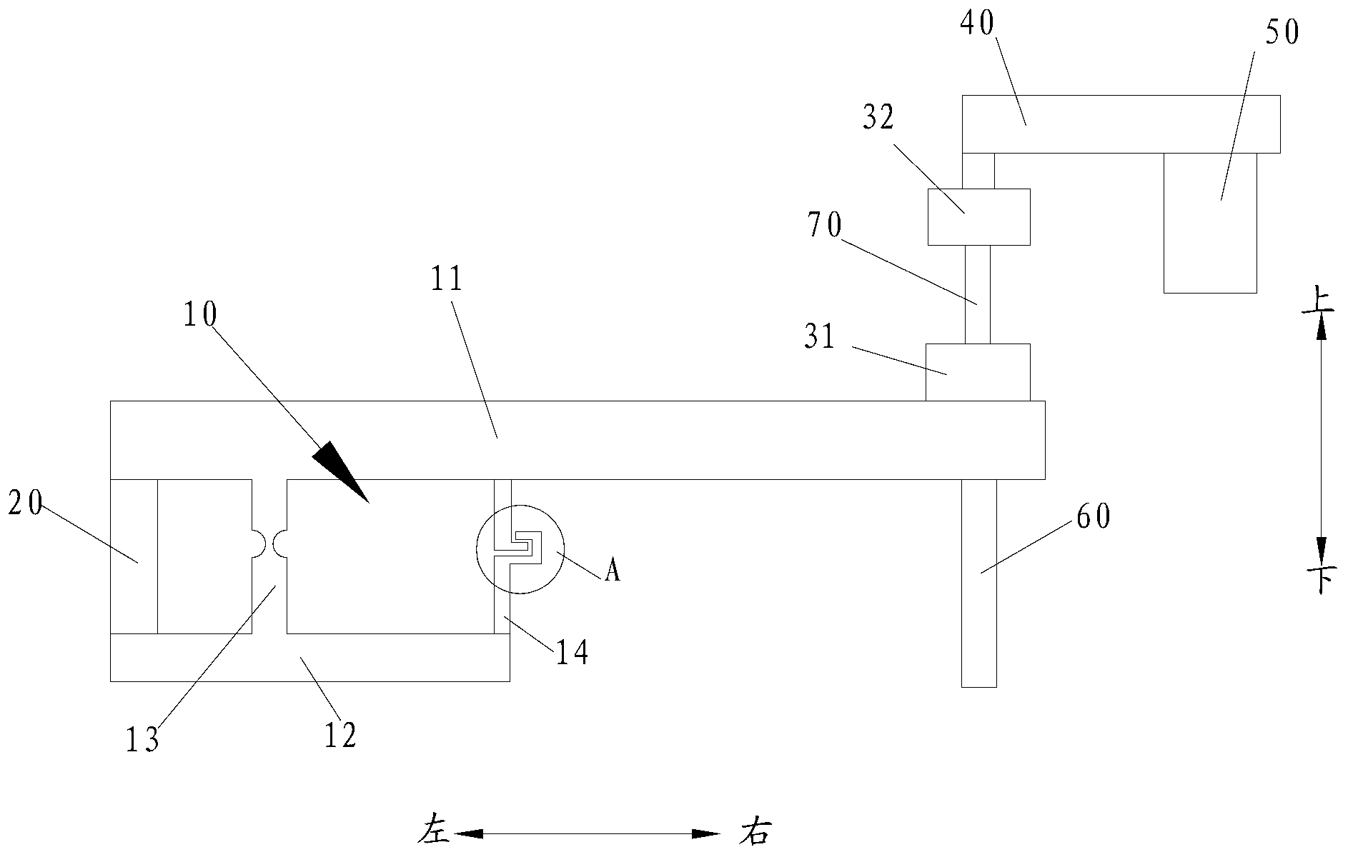
[0066] The parameters of each component are: the maximum linear displacement of the piezoelectric ceramic 20 is 22 μm; the maximum displacement load of the lever assembly 10 is 110 μm; the maximum measuring range of the sensor 40 is 1N, and the precision is 0.0005N.

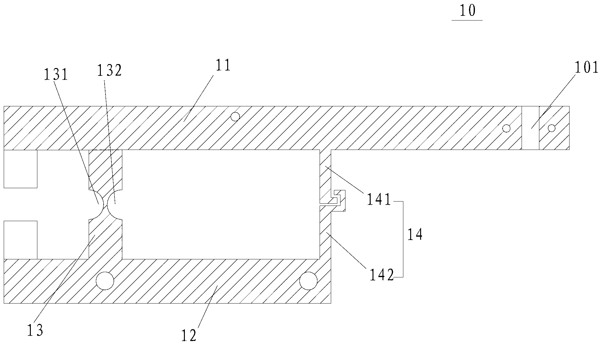
[0067] Such as figure 1 with figure 2 As shown, the device is composed of a lever assembly 10, a piezoelectric ceramic 20, an initial trimmer 50, a film 70, a sensor 40, a guide rail 60 and an external control port (not shown). Typical samples, such as optical fiber samples, plastic films, etc., are pasted on the first clamping piece 31 and the second clamping piece 32 with epoxy glue. During the experiment of the present invention, the force load of the thin film 70 increases uniformly with the increase of the driving voltage of the piezoelectric ceramic 20, and the device has good linearity and high reliability.

Embodiment 2

[0069] Fabricate an aluminum frame with a thin film specimen (eg image 3 ) is fixed on the film loading device with four screw holes, and then the aluminum frame is cut off with a high-speed grinding wheel, so that the film specimen can bear the force load alone. Cutting the edge of the frame causes less vibration than cutting the middle, which is beneficial to protect the film specimen. The loading device was then placed inside a scanning electron microscope for tensile testing. In the tensile test, the load data is obtained by the micro force sensor, and the displacement and strain of the thin film specimen are calculated by the moiré method of the scanning electron microscope. The elastic modulus of the specimen measured by the scanning electron microscope moiré method is 72.1 GPa.


PUM

PropertyMeasurementUnit
Elastic modulusaaaaaaaaaa

Abstract

The invention discloses a film loading device which comprise a bracket, a lever assembly, piezoelectric ceramic, a first clamping piece, a second clamping piece and a sensor, wherein the lever assembly comprises a movable rod which is rotatably arranged on the bracket around a preset point; the piezoelectric ceramic is connected with the movable rod for inputting initial displacement to the movable rod; the first clamping piece is connected with the movable rod; the first clamping piece is used for clamping the first end of a film and the second clamping piece is used for clamping the second of the film; the distance from the joint of the first clamping piece and the movable rod to the preset point is longer than the distance from the joint of the piezoelectric ceramic and the movable rod to the preset joint; and the sensor is used for measuring tensile force applied to the film, is arranged on the bracket and is connected with the second clamping piece. The film loading device provided by the invention is high in loading placement accuracy, rapid to respond, large in output displacement and simple in structure.

Description

technical field [0001] The invention relates to the technical field of design and manufacture of precision measuring instruments, in particular to a film loading device. Background technique [0002] As the most commonly used mechanical property test method, uniaxial tensile test can measure parameters such as stress-strain curve, elastic modulus, Poisson's ratio and strength of the film. In recent years, with the continuous deepening of research on thin film (filament) materials, it has become necessary to fully understand the macro and micro mechanical properties of materials. [0003] There are three main driving modes for micro-tensile loading of film specimens: electromagnetic force driving, stepping motor driving and piezoelectric ceramic driving. (1) Driven by electromagnetic force. When current passes through the electromagnetic coil, the generated electromagnetic force drives the relative motion between the permanent magnet and the electromagnetic coil, thereby st...

Claims


Application Information

Patent Timeline
IPC IPC(8): G01N3/08
Inventor 谢惠民朱荣华唐敏锦戴相录
Owner TSINGHUA UNIV
Why Eureka
Try Eureka