Moving-coil type electro-acoustic transducer
An electro-acoustic converter and moving coil technology, applied in the direction of sensors, electrical components, etc., can solve the problems of sacrificing product power, limiting magnetic flux, occupying size space, etc., to ensure the output acoustic performance, increase the effective vibration area, improve The effect of magnetic flux
- Summary
- Abstract
- Description
- Claims
- Application Information
AI Technical Summary
Problems solved by technology
Method used
Image
Examples
Embodiment 1
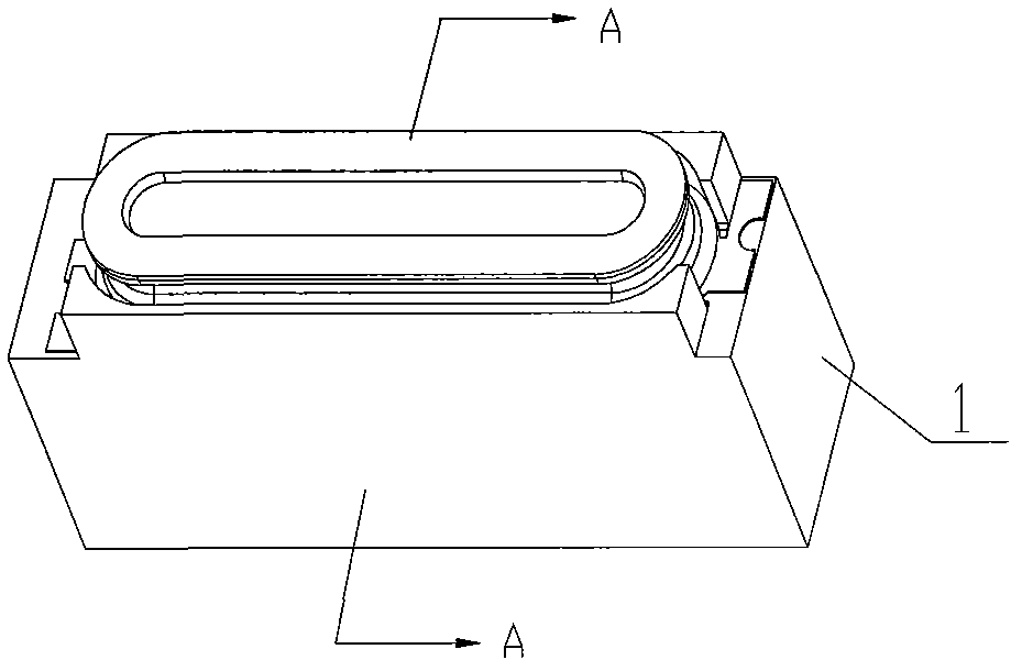
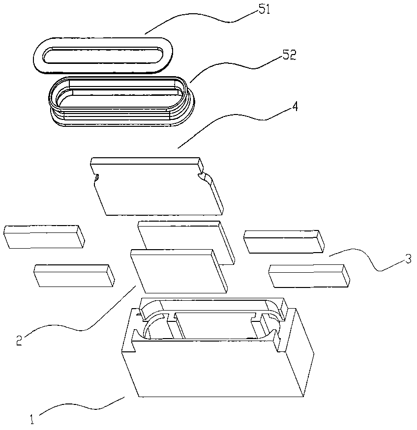
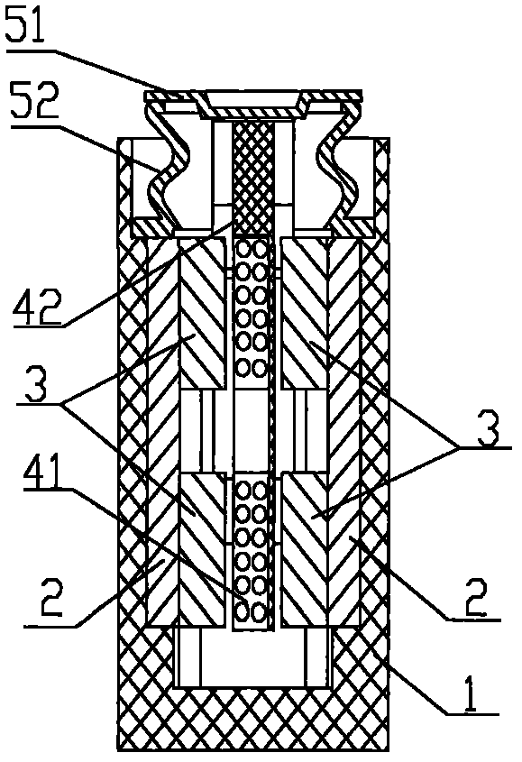
[0030] figure 1 It is a perspective view showing the moving coil electroacoustic transducer involved in this embodiment; figure 2 The formula represents the decomposition diagram of the dynamic electro-acoustic transducer; image 3 yes means figure 1 A-A to the sectional view. Such as figure 1 , figure 2 and image 3 As shown, the moving coil electroacoustic transducer provided by the present invention has a long strip structure and mainly includes a housing 1, a vibration system and a magnetic circuit system. The housing 1 fixedly combines the vibration system and the magnetic circuit system.
[0031] The vibration system includes a long vibrating plate composed of a rigid central part 51 and a flexible ring part 52 , and a driving device composed of a flat voice coil barrel 41 and a voice coil support 42 correspondingly fixed to the voice coil barrel 41 . Wherein one end of the ring part 52 is airtightly connected and supports the center part 51, and the other end is...
Embodiment 2
[0037] Figure 9 It is a schematic cross-sectional view showing the combination of the magnetic circuit system of the moving-coil electro-acoustic transducer involved in the second embodiment, the voice coil tube and the voice coil support; as Figure 9 As shown, the main difference between this embodiment and the above-mentioned embodiments is that the magnetic circuit system in this embodiment includes a set of oppositely arranged magnets 3 with opposite polarities, and the end of the magnetic guide plate 2' close to the voice coil tube 41 is provided with a Make the magnetic guide plate 2 ′ close to the protrusion of the voice coil barrel 41 . In this example, the magnetic flux at the long axis of the upper end of the voice coil tube 41 corresponding to the magnet 3 mainly comes from the two opposite magnets 3, while the magnetic flux at the long axis of the lower end mainly comes from the protruding part through which the magnetic guide plate 2' passes. Conduction, thus f...
Embodiment 3
[0040] Figure 10 It is a schematic cross-sectional view showing the combination of the magnetic circuit system of the moving coil electro-acoustic transducer involved in the third embodiment, the voice coil cylinder and the voice coil support, as Figure 10 As shown, the main difference between this implementation process and the above-mentioned implementation process is that the structure of the magnetic conductive plate 2 "is different. Close to the bending of the voice coil tube 41, the magnetic guide plate 2" increases the magnetic flux at the long axis of the lower end of the voice coil tube 41 through this bending. This design scheme can also achieve the technical effect of the above-mentioned implementation process, and can satisfy More production design needs.
PUM
 Abstract
Description
Claims
Application Information
 - R&D
- Intellectual Property
- Life Sciences
- Materials
- Tech Scout
- Unparalleled Data Quality
- Higher Quality Content
- 60% Fewer Hallucinations
Browse by: Latest US Patents, China's latest patents, Technical Efficacy Thesaurus, Application Domain, Technology Topic, Popular Technical Reports.
© 2025 PatSnap. All rights reserved.Legal|Privacy policy|Modern Slavery Act Transparency Statement|Sitemap|About US| Contact US: help@patsnap.com


