Rod reducer apparatus for spinal corrective surgery

A technology of spinal rod and reducer, applied in the direction of fixator, internal fixator, fastening device, etc., can solve the problem of high implantation cost and so on

Inactive Publication Date: 2011-11-23
SYNTHES GMBH
View PDF2 Cites 3 Cited by
  • Summary
  • Abstract
  • Description
  • Claims
  • Application Information

AI Technical Summary

Problems solved by technology

However, this technique is typically limited to reduction screws and results in expensive implantation

Method used


Image

  • Rod reducer apparatus for spinal corrective surgery
  • Rod reducer apparatus for spinal corrective surgery
  • Rod reducer apparatus for spinal corrective surgery

Examples


Embodiment Construction

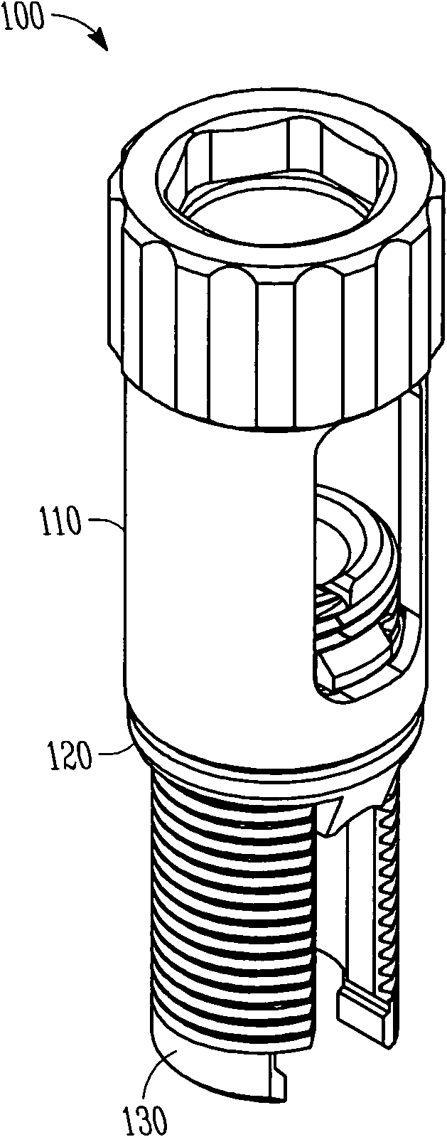
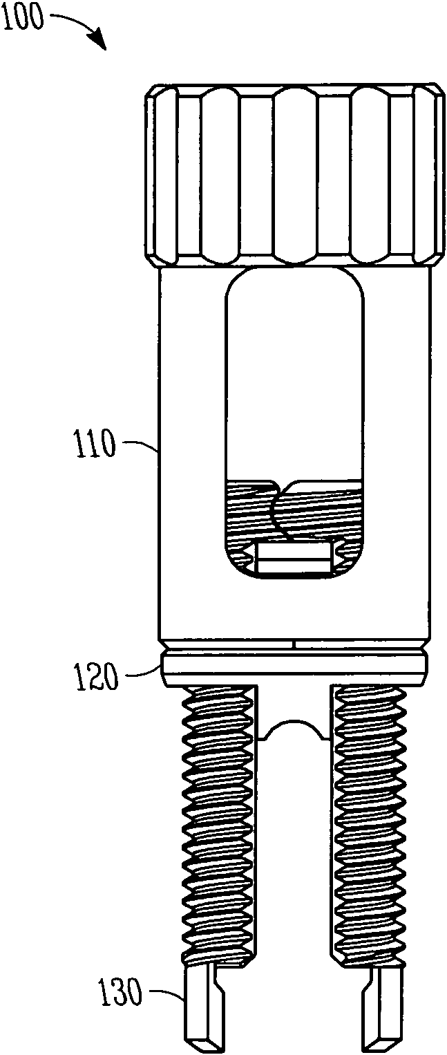
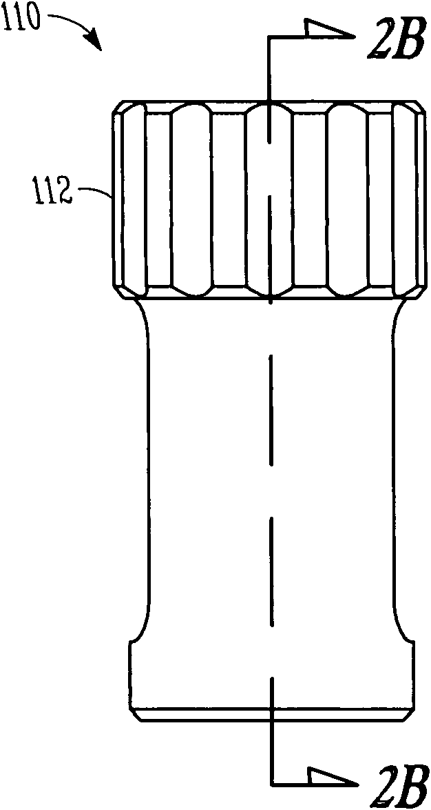
[0054] The present inventors have recognized that, among other considerations, it is desirable to construct a simplified, externally mounted mini-reduction instrument that can be used in any hook- or screw-like device (including single-axis, multi- shaft and sagittal screws), and can be reused, reshaped, or removed as needed at any time during the entire course of spinal correction surgery.

[0055] Certain terms are used hereinafter for convenience only and not for limitation. The words "right", "left", "below" and "upper" designate directions in the figures to which reference is made. The words "inwardly" or "distal" and "outwardly" or "proximally" refer to directions toward and away from, respectively, the geometric center or orientation of the instrument assembly and its associated components. The words "anterior", "posterior", "superior", "inferior", "lateral" and related words and / or expressions indicate preferred positions and orientations in the human body with refere...


PUM


Abstract

Spinal rod reduction apparatuses, systems, and methods are provided. In various examples, a rod reduction apparatus includes a first threaded member (130, 210, 330) including an engagement feature (138A, 138B, 220, 332, 334) configured to selectively anchor the first threaded member to the implantable screw assembly. A second threaded member (110, 230, 310) is configured to threadably engage with the first threaded member. The second threaded member is axially movable with respect to the first threaded member with rotation of the second threaded member. A spinal rod urging member (120, 240, 320) is axially movable with the second threaded member. The urging member includes a bearing surface (126, 242, 320) that is configured to selectively abut the spinal rod and selectively urge the spinal rod toward the implantable screw assembly with rotation of the second threaded member in a first rotational direction.

Description

technical field [0001] This patent document relates generally to the field of orthopedic surgery. More specifically (but not limitingly), this patent document relates to an apparatus and method for correction of spinal deformities. Background technique [0002] In the field of spinal surgery, several techniques exist for reducing the spinal rod into posterior pedicle screws. The most basic technique uses a separate rod-resetting instrument (such as a rocker fork or a pawl-type device designed to reset the rod one stage at a time) after insertion. The screw and placement rod are then coupled to the head of the screw, ie to each pedicle screw respectively. Such a segmental reduction technique will generate a large axial load on the pedicle screw. [0003] Alternatively, the rod can yield to a particular deformity and then seat within an implanted pedicle screw. Once seated, the deformity can be corrected by bending the rod in place. This technique can be time consuming an...

Claims


Application Information

Patent Timeline
Patent Type & Authority Applications(China)
IPC IPC(8): A61B17/88
CPCA61B17/7086A61B17/70A61B17/84A61B17/86A61B17/88A61B17/7085
Inventor D·拉思本B·德克M·道布斯
Owner SYNTHES GMBH
Why Eureka
Try Eureka