Refrigeration device

A technology for refrigeration appliances and refrigerant circuits, which is applied to household refrigeration devices, coolers, defrosting, etc., and can solve problems such as size restrictions

Active Publication Date: 2011-11-23
BSH BOSCH & SIEMENS HAUSGERAETE GMBH
View PDF5 Cites 7 Cited by
  • Summary
  • Abstract
  • Description
  • Claims
  • Application Information

AI Technical Summary

Problems solved by technology

However, the size of the contact surfaces is limited in conventional refrigeration appliances for assembly reaso...

Method used


Image

  • Refrigeration device
  • Refrigeration device
  • Refrigeration device

Examples


Embodiment Construction

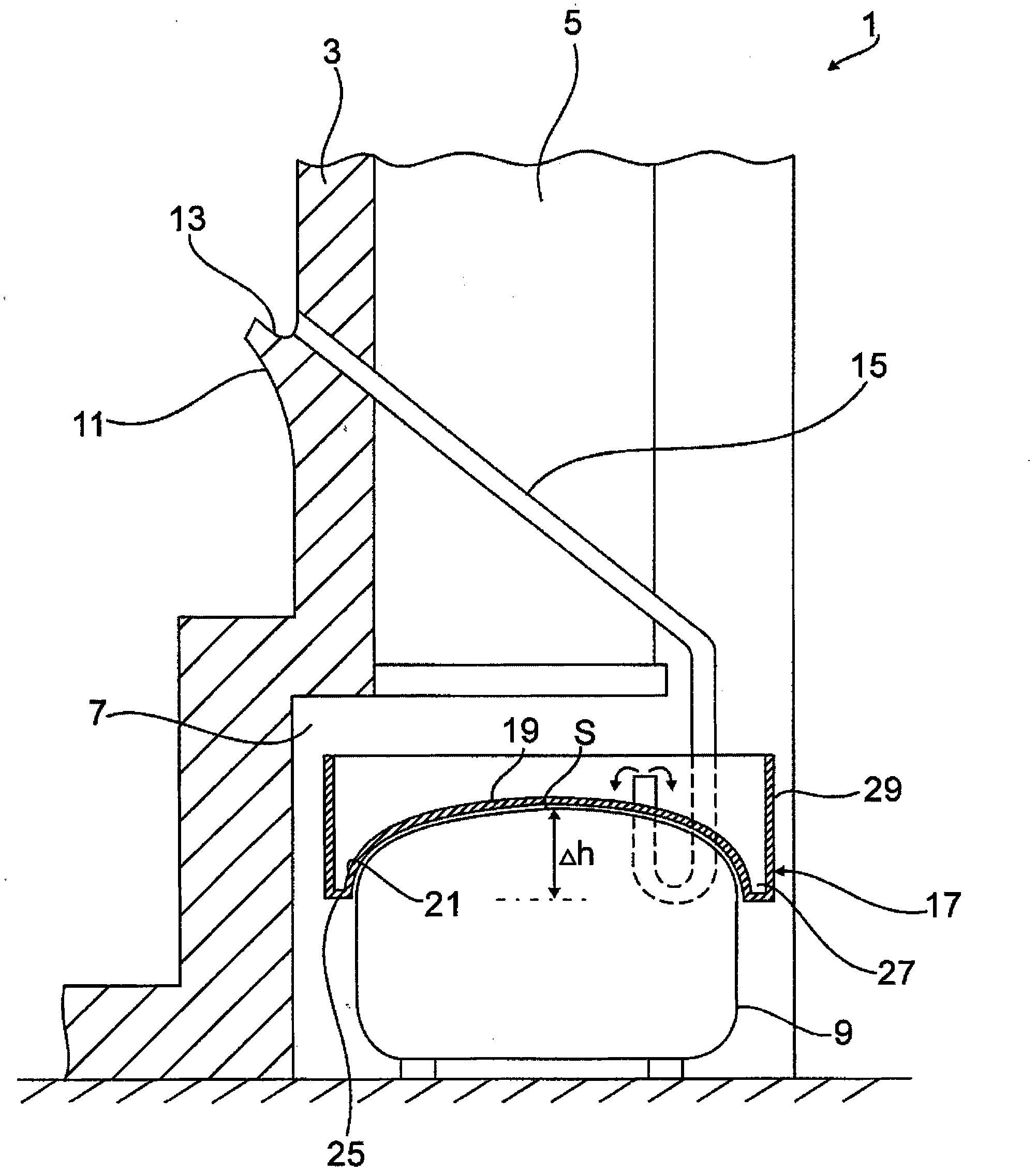
[0024] figure 1 A schematic partial view of the rear region of the appliance housing 1 of the cooling appliance is shown. The housing 1 is provided with a condenser 5 (shown only in outline), which is located on the rear wall 3 in a known manner. The condenser is part of the refrigerant circuit and is used to cool the refrigerator compartment of the refrigeration appliance. Close to the bottom, the rear wall 3 has a cutout 7 in which the compressor 9 of the refrigerant circuit is seated.

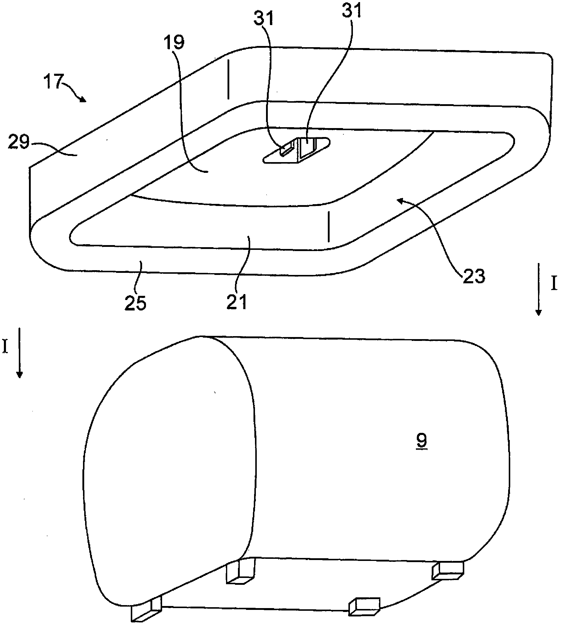
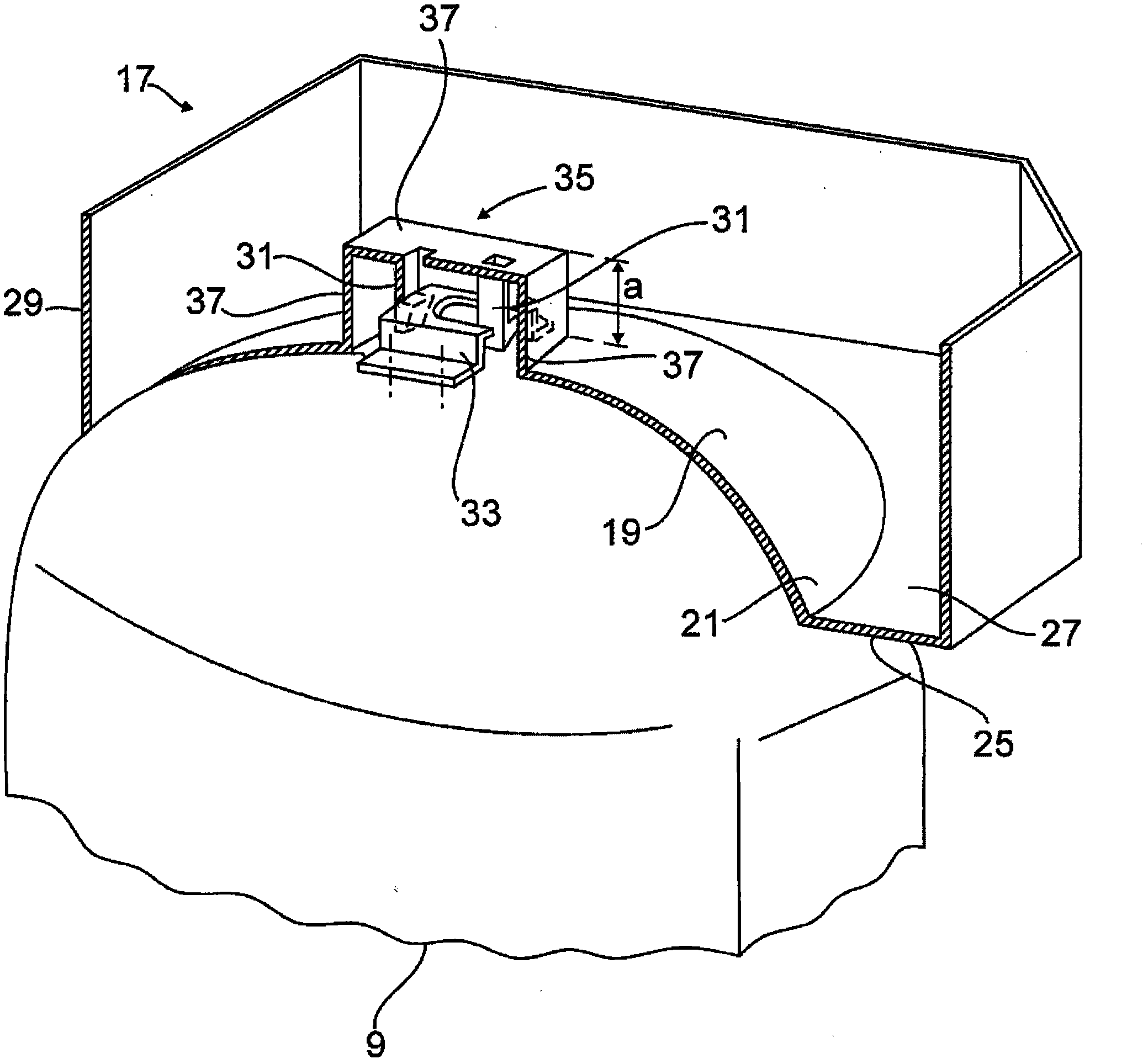
[0025] During the cooling operation, water condenses and freezes on the inner surface of the housing rear wall 3 . In order to collect condensed water during defrosting, a wall projection 11 is molded on the housing inner wall 3 inside the housing, which forms a defrosting water channel 13 . The defrost water channel 13 is fluidly connected by means of a condensation line 15 to a condensation collection container 17 which is seated on top of the compressor 9 outside the housing interior. ...


PUM


Abstract

The invention relates to a refrigeration device, in particular a domestic refrigeration device comprising a compressor (9) that is connected in a refrigeration circuit and a condensation collection container (17) that collects the condensation formed during the operation of the refrigeration device, the base (19) of said container sitting on an upper face of the compressor (9). According to the invention, the base (19) of the condensation collection container (17) is designed with a lateral wall (21) that extends downwards and surrounds the sides of the compressor (9).

Description

technical field [0001] The invention relates to a refrigeration appliance, in particular a domestic refrigeration appliance, according to the preamble of claim 1 ; a condensation collection container according to claim 14 ; and a method of assembling a refrigeration appliance according to claim 15 . Background technique [0002] The refrigerating appliance has a refrigerating chamber closed by a thermally insulating housing and cooled by the evaporator of the refrigerant circuit. Condensate deposits on correspondingly cooled surfaces of the refrigerator compartment, collects inside the housing and is conducted away from the housing by means of condensation lines. [0003] In addition to the evaporator, conventional refrigerating appliances also have a compressor connected to a matching condensate collection container in the refrigerating circuit. The container collects condensate formed during operation of the refrigeration appliance, and the container bottom of the contain...

Claims


Application Information

Patent Timeline
IPC IPC(8): F25D21/14
CPCF25D2321/143F25D21/14F25D2321/1411Y10T29/49359F25D19/00
Inventor F·J·弗洛雷斯曼乔
Owner BSH BOSCH & SIEMENS HAUSGERAETE GMBH
Why Eureka
Try Eureka