
Transdermal irradiation device for guiding trachea intubation by using regressive light

A technology of endotracheal intubation and light guidance, applied in the direction of endotracheal intubation, surgical lighting, medical science, etc., can solve problems that are difficult to master, difficult, and not very familiar with, and achieve good exposure of the glottis and convenient intubation Effect

Inactive Publication Date: 2013-04-03
SECOND MILITARY MEDICAL UNIV OF THE PEOPLES LIBERATION ARMY
View PDF5 Cites 0 Cited by
  • Summary
  • Abstract
  • Description
  • Claims
  • Application Information

AI Technical Summary

Problems solved by technology

Traditional direct laryngoscope exposure for endotracheal intubation is a difficult technique to master, and it is difficult for medical staff without formal training. The effect of directional light on the positioning of the glottis is limited, so it is urgent to find a new type of irradiation device that can clearly locate the position of the tracheal intubation in clinical practice

Method used


Image

  • Transdermal irradiation device for guiding trachea intubation by using regressive light
  • Transdermal irradiation device for guiding trachea intubation by using regressive light

Examples


Embodiment 1

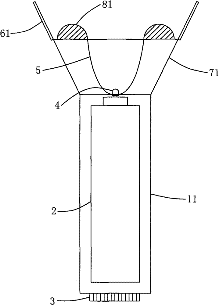
[0019] Such as figure 1 As shown, the device includes a cylinder 11, a power supply 2, a lamp bead 4, a lampshade 71, a support baffle 61, a pressing protrusion 81 and a switch 3, the power supply 2 is arranged in the inner cavity of the cylinder 11, the power supply 2, the lamp bead 4 and The switch 3 is electrically connected, the switch 3 is arranged at the tail end of the barrel 11, and the irradiation intensity can be continuously adjusted, the barrel 11 is cylindrical, the lamp bead 4 is arranged at the head end of the barrel 11, and the support baffle 61 is made of elastic material, such as Silicone, plastic, rubber and other elastic and flexible supporting materials, the thickness is slightly thicker than the lampshade 71, and it is arranged on the head end of the lampshade 71 edge. The baffle 61 has a certain hardness, which can press the cricoid cartilage, better expose the glottis, and facilitate intubation.

[0020] The lampshade 71 is in the shape of a truncated ...

Embodiment 2

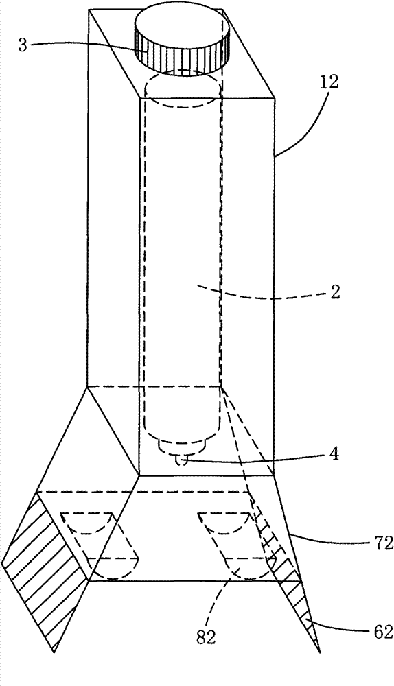
[0022] Such as figure 2 As shown, the device includes a cylinder 12, a power supply 2, a lamp bead 4, a lampshade 72, a support baffle 62, a pressing protrusion 82 and a switch 3, the power supply 2 is arranged in the inner cavity of the cylinder 12, the power supply 2, the lamp bead 4 and The switch 3 is electrically connected, the switch 3 is arranged at the tail end of the barrel 12, the barrel 12 is in the shape of a cuboid, the lamp bead 4 is arranged at the head end of the barrel 1, and the support baffle 62 is made of elastic material, such as silica gel, plastic, rubber, etc. The elastic and flexible supporting material is arranged on the edge of the head end of the lampshade 72 .

[0023] The lampshade 72 is in the shape of a quadrangular truss with diffused head end, and the support baffle plate 62 is two trapezoidal segments, which are arranged on the opposite sides of the head end edge of the lampshade 72, that is, extending from the two sides of the lampshade 72 ...


PUM


Abstract

The invention discloses a transdermal irradiation device for guiding trachea intubation by using regressive light. The device comprises a barrel body, a power supply, a lamp bead, a lampshade, a support baffle plate, a press bump and a switch, wherein the power supply is arranged in the cavity of the barrel body; the power supply, the lamp bead and the switch are electrically connected with one another; the lamp bead is arranged at the head end of the barrel body; the press bump is made of a hard material and is positioned on the inner side of the support baffle plate; the support baffle plate is made of a material with certain elasticity, and is arranged at the head end of the lamp cap; and the tail end of the lampshade is in threaded connection with the barrel body. The transdermal irradiation device can be used for guiding trachea intubation by using regressive light, so that an intubation position can be quickly found conveniently; and the device is particularly suitable for medical personnel who do not receive formal training.

Description

【Technical field】 [0001] The invention relates to an auxiliary medical device, in particular to an irradiation device for tracheal intubation operation. 【Background technique】 [0002] During clinical tracheal intubation, the light emitted by the light-emitting device of the laryngoscope is used to guide the intubation. This requires the doctor to be very familiar with the anatomical structure of the glottis in order to complete it smoothly. Traditional direct laryngoscope exposure for endotracheal intubation is a difficult technique to master, and it is difficult for medical staff without formal training. The effect of phototropism on the positioning of the glottis is limited, so it is urgent to find a new type of irradiation device that can clearly locate the position of the tracheal intubation in clinical practice. 【Content of invention】 [0003] The technical problem to be solved by the present invention is to provide a device that can clearly locate the position of t...

Claims


Application Information

Patent Timeline
Patent Type & Authority Patents(China)
IPC IPC(8): A61B1/00A61B19/00A61B90/30A61M16/04
Inventor 杨涛
Owner SECOND MILITARY MEDICAL UNIV OF THE PEOPLES LIBERATION ARMY
Learn More