
Vertical elastic tension and compression support

An elastic and vertical technology, applied in the direction of bridge parts, bridge materials, bridges, etc., can solve problems such as the inability to meet the construction requirements of large-scale suspension cable bridges, and the inability of bearings to bear pressure and horizontal displacement at the same time.

Active Publication Date: 2011-11-30
XINJIN TENGZHONG ROAD CONSTR MACHINERY
View PDF8 Cites 18 Cited by
  • Summary
  • Abstract
  • Description
  • Claims
  • Application Information

AI Technical Summary

Problems solved by technology

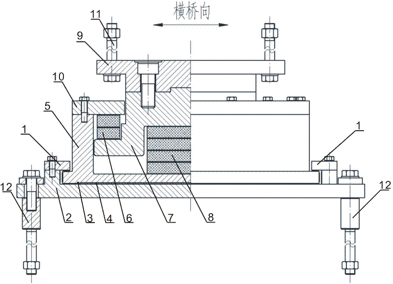
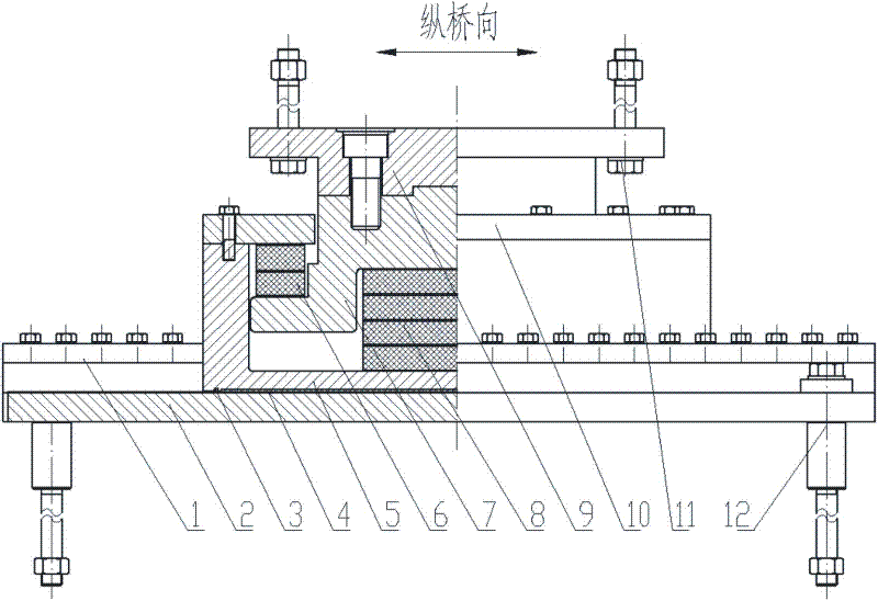
[0007] The purpose of the present invention is to provide a vertical support for the existing supports that cannot simultaneously have functions such as pressure bearing, horizontal displacement, tension bearing, and displacement in the direction of force (vertical), so that they cannot meet the construction requirements of large suspension cable bridges. Elastic tension and compression support

Method used


Image

  • Vertical elastic tension and compression support
  • Vertical elastic tension and compression support
  • Vertical elastic tension and compression support

Examples


Embodiment Construction

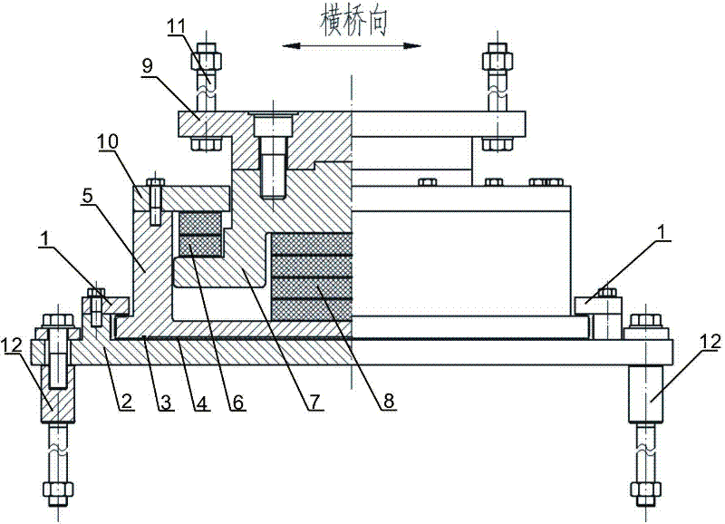
[0027] Such as figure 1 , 2 Shown: vertical elastic tension-compression support, which includes pressure plate 1, slide plate 2, elastic sealing ring 3, wear-resistant plate 4, steel basin 5, tension damper 6, middle steel lining plate 7, pressure damper 8 , Top plate 9, pressure ring 10, upper anchoring device 11, lower anchoring device 12. An upper anchoring device 11 is fixed on each corner of the upper end surface of the top plate 9 , and a lower anchoring device 12 is fixed on each corner of the bottom surface of the slide plate 2 , a steel basin 5 is arranged above the slide plate 2 , and a pressure ring 10 is fixed on the top of the steel basin 5 . The pressure plate 1 is fixed on both sides of the slide plate 2, a wear plate 4 is provided between the slide plate 2 and the steel basin 5, and an elastic sealing ring 3 is provided around the wear plate 4; a pressure damper 8 is provided in the center of the steel basin 5 , the top of the pressure damper 8 is fixed with ...


PUM


Abstract

The invention discloses a vertical elastic tension compression support. The vertical elastic tension compression support comprises pressure plates, a sliding plate, an abrasion-resistant plate, a steel basin, a tension damper, an intermediate steel lining plate, a compression damper, a top plate, a compression ring, upper anchoring devices and lower anchoring devices, wherein the upper anchoring devices are fixed at the corners of the upper end face of the top plate; the lower anchoring devices are fixed at the corners of the bottom surface of the sliding plate; the steel basin is arranged above the sliding plate; and the compression ring is fixed at the top of the steel basin. The vertical elastic tension compression support is characterized in that: the pressure plates are fixed at two sides of the sliding plate, the abrasion-resistant plate is arranged between the sliding plate and the steel basin, and elastic sealing rings are arranged at four sides of the abrasion-resistant plate; and the compression damper is arranged in the middle in the steel basin, the intermediate steel lining plate is fixed at the top of the compression damper, the tension damper is arranged between theintermediate steel lining plate and the compression ring, and the top of the intermediate steel lining plate passes through the compression ring and is fixedly connected with the top plate. By adopting the vertical elastic tension compression support, a bridge can move and is not in a suspended state at the support; meanwhile, in the vertical displacement process, the rigidity coefficient of the support meets the design requirement; and after the support vertically reaches the predetermined displacement, the support is limited by a limiting device.

Description

technical field [0001] The invention belongs to the technical field of bridge supports, in particular to a tension-compression support capable of simultaneously satisfying vertical load and vertical displacement. Background technique [0002] The bridge bearings used in bridge construction include plate rubber bearings and pot rubber bearings, among which pot rubber bearings are widely used due to their superior performance. However, the existing pot-type rubber bearings cannot meet the composite displacement requirements of large-scale suspension bridges, especially in the direction of vertical force displacement. And the bearings that can be displaced in the direction of force are not completely absent. For example, the plate rubber bearing is one of them. It can have a certain displacement under shear conditions, but the relative size of this displacement is extremely small, which cannot meet the requirements of large suspension bridges at all. [0003] The existing ten...

Claims


Application Information

Patent Timeline
IPC IPC(8): E01D19/04E01D101/40
Inventor 欧阳先凯罗启杨光旭
Owner XINJIN TENGZHONG ROAD CONSTR MACHINERY
Learn More