
Electric valve

An electric valve and valve seat technology, applied in the field of electric expansion valve, can solve the problems of electric valve action performance decline, no balance channel, etc., and achieve the effect of reliable action performance

Inactive Publication Date: 2011-11-30
ZHEJIANG SANHUA INTELLIGENT CONTROLS CO LTD
View PDF5 Cites 10 Cited by
  • Summary
  • Abstract
  • Description
  • Claims
  • Application Information

AI Technical Summary

Problems solved by technology

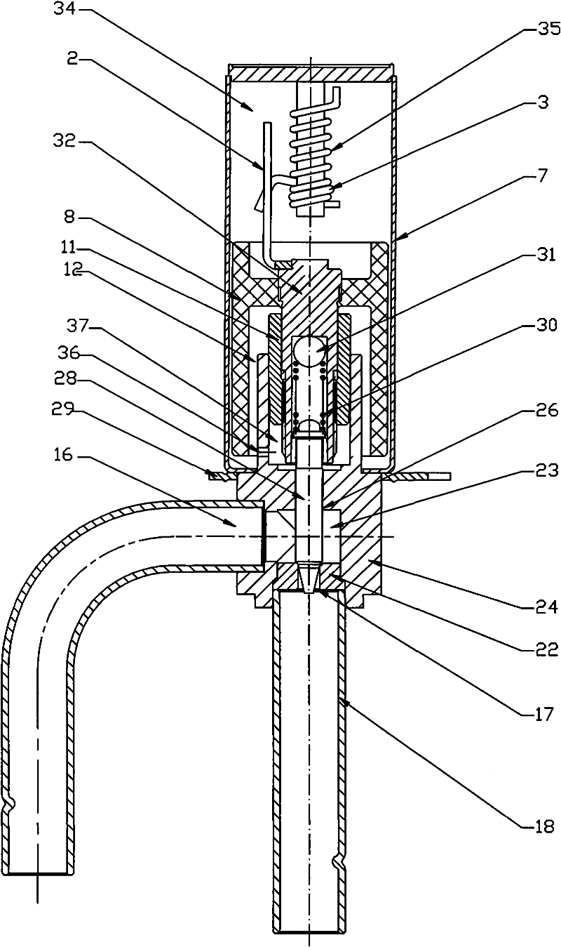
[0004] In the prior art, the valve port 17 is arranged on the small valve seat 22, and the small valve seat is fixed on the valve seat 24, so that the assembly relationship of the two parts will cause a certain amount of radial coaxiality of the valve port. In addition, although the second part of the valve cavity 12 communicates with the inner cavity 37 formed between the nut 11 and the cylindrical part of the valve seat through the balance hole 36, there is no balance channel between the inner cavity 37 and the valve seat cavity 23 , so that the pressure of the valve seat cavity 23 communicating with the inlet pipe 16 is greater than the pressure of the valve cavity formed by the valve seat and the shell, so that when some refrigerants with high pressure difference are used, the action performance of the electric valve may be reduced

Method used


Image

  • Electric valve
  • Electric valve
  • Electric valve

Examples


Embodiment Construction

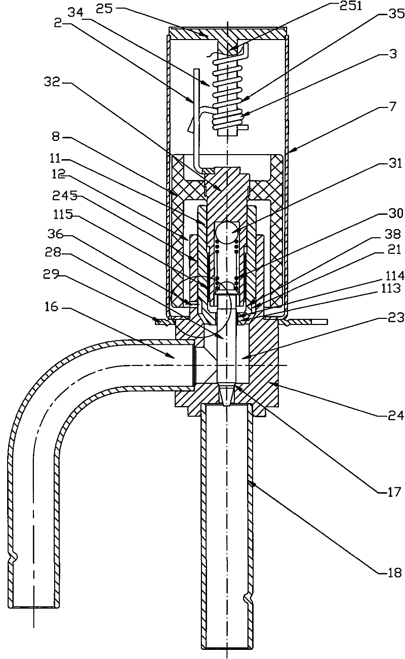
[0020] In order to enable those skilled in the art to better understand the technical concept of the present invention, the present invention will be further described in detail below in conjunction with the accompanying drawings and specific embodiments.

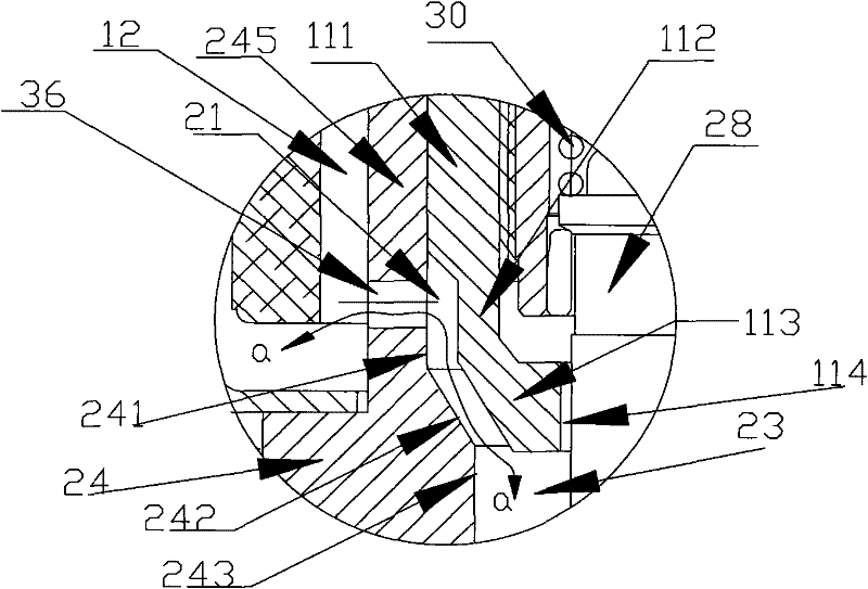
[0021] in, figure 2 It is a structural schematic diagram of an embodiment of the electric valve of the present invention, image 3 for figure 2 Schematic diagram of the partially enlarged structure of the electric valve. As shown in the figure, the electric valve includes a valve seat 24, a housing 7 connected and fixed to the valve seat 24, and an inlet pipe 16 and an outlet pipe 18 connected and fixed to the valve seat 24, and the inlet pipe 16 and the outlet pipe 18 are connected to the valve seat. The position forms the inlet and outlet of the electric valve; the inlet of the electric valve is connected to the refrigeration system through the inlet pipe 16, and the outlet is connected to the refrigeration system thr...


PUM


Abstract

The invention discloses an electric valve, which relates to the throttling control of refrigerant in a refrigeration system. The electric valve includes a valve seat, a shell connected and fixed to the valve seat, an inlet and an outlet, and a valve seat cavity and the valve seat are arranged inside the valve seat. The valve port between the inlet and the outlet, a valve chamber is formed in the housing, a magnetic rotor part is arranged in the valve chamber, the valve seat includes a cylindrical part extending into the valve chamber, and the cylinder A nut is fixed on the shaped part, and a pressure balance passage is set between the cylindrical part of the valve seat in the valve cavity and the housing to the valve seat cavity communicating with the inlet, so that The action performance of the electric valve is more reliable, especially more suitable for the use of new refrigerants with relatively high pressure.

Description

technical field [0001] The invention relates to the technical field of refrigeration control, in particular to an electric expansion valve for controlling throttling and expansion of refrigerant. Background technique [0002] The electric expansion valve (or electric valve) installed in the refrigeration cycle system as a flow control valve, such as figure 1 As shown, it includes an electric valve body and a coil (not shown) outside the outer cover of the electric valve body: the electric valve body includes a valve seat 24 and two connecting pipes connected to the valve seat 24: the inlet pipe 16 , the outlet pipe 18, the valve seat 24 is provided with a valve seat chamber 23 and is fixed with a small valve seat 22, the small valve seat 22, the connecting pipe and the valve seat are fixed by welding, and the small valve seat 22 is also provided with a valve seat located between the two connecting pipes. The valve port 17 between; the valve seat 24 is also provided with a t...

Claims


Application Information

Patent Timeline
Patent Type & Authority Applications(China)
IPC IPC(8): F25B41/06
CPCY02B30/72Y02B30/70
Inventor 不公告发明人
Owner ZHEJIANG SANHUA INTELLIGENT CONTROLS CO LTD
Learn More