refrigerator

A technology of refrigerators and opening and closing bodies, applied in the field of refrigerators, can solve the problems of baffle device resistance, storage space reduction, no consideration, etc., and achieve the effect of improving energy saving performance and air supply efficiency

Inactive Publication Date: 2011-11-30
HITACHI APPLIANCES INC
View PDF7 Cites 14 Cited by
  • Summary
  • Abstract
  • Description
  • Claims
  • Application Information

AI Technical Summary

Problems solved by technology

[0008] However, in the damper devices described in Patent Document 1 and Patent Document 2, when shifting from a fully open state in which both openings are open to a fully closed state in which both openings are closed, they can only be closed one by one.
Therefore, there is a problem that the time for both openings to be fully closed from fully open becomes long.
[0009] In addition, when the baffle devices described in the above-mentioned Patent Document 1 and Patent Document 2 are installed on the refrigerator, if the positional relationship with the blower and the storage room is not considered, the storage space will be reduced, and the baffle device will be damaged during ventilation. danger of becoming resistance

Method used


Image

  • refrigerator
  • refrigerator
  • refrigerator

Examples


Embodiment 1

[0066] The overall structure of the refrigerator

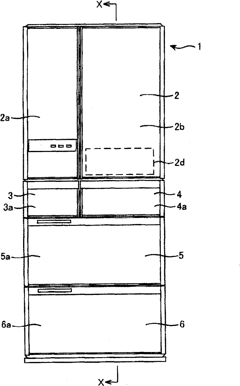
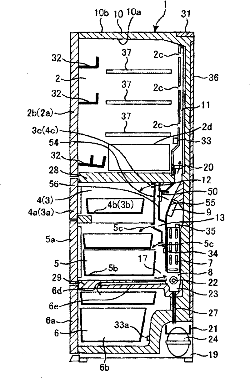
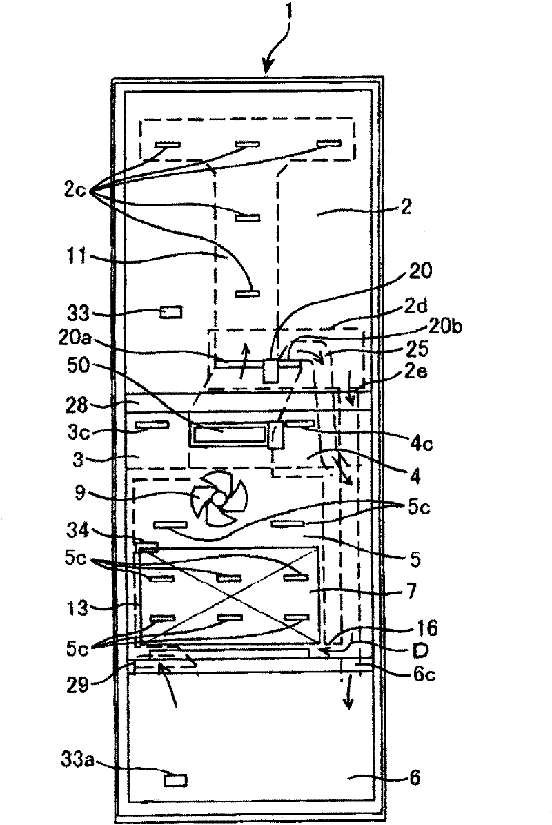
[0067] figure 1 It is a front external view of the refrigerator of this embodiment. figure 2 Indicates the structure of the refrigerator figure 1 X-X longitudinal section view. image 3 It is a front view showing structure in the box of the refrigerator. Figure 4 yes figure 2 The main enlarged explanatory diagram of is a diagram showing the arrangement of the cold air passage and the outlet.

[0068] Such as figure 1 As shown, the refrigerator 1 of this embodiment has the refrigerator compartment 2, the ice making compartment 3, the upper freezer compartment 4, the lower freezer compartment 5, and the vegetable compartment 6 sequentially from above. As an example, the refrigerator compartment 2 and the vegetable compartment 6 are storage rooms in a refrigeration temperature range whose temperature is about 3 to 5°C. In addition, the ice-making compartment 3, the upper freezer compartment 4, and the lower freezer comp...

Embodiment 2

[0213] Below, refer to Figure 35 to Figure 39 Example 2 will be described. Figure 35 is in Embodiment 2 figure 1 The X-X section view. Figure 36 It is a schematic diagram explaining the positional relationship of the air blower and cooler when the double damper which has this invention is attached to a refrigerator in Embodiment 2. Figure 37 is used Figure 36 This is a diagram illustrating the positional relationship between the double baffles and the blower. Figure 38 yes Figure 37 The A-B line section is equivalent to the explanatory diagram. Figure 39 yes Figure 37 The C-B line section is equivalent to the explanatory diagram.

[0214] Here, when the ventilation control of the storage room in the freezing temperature zone and the storage room in the refrigerating temperature zone is performed by a double baffle device, the baffle device is provided behind the storage room in the freezing temperature zone. That is, the double baffle device is provided in the...


PUM


Abstract

The invention aims discloses a refrigerator and aims to improve the air supplying efficiency by using a baffle device and improve the energy saving performance. The refrigerator is provided with a first frame of a first opening sending cool air to a first air supply channel; a second frame of a second opening sending cool air to a second air supply channel; a first and a second cover respectively open or close the first and the second opening; and a drive mechanism disposed between the first frame and the second frame and driving the first cover ant the second cover. A first drive shaft is disposed on one side of the first cover, and a second drive shaft is disposed on an opposite side of the first cover. The upper end of an air supplier is disposed below an intersection point of the rotation paths of the first cover and the second cover and above the lowest point of the rotation paths of the first cover and the second cover.

Description

technical field [0001] The present invention relates to a refrigerator with a baffle device. Background technique [0002] Conventionally, there are storage rooms in the refrigerating temperature zone and storage rooms in the freezing temperature zone, and the cold air that has been heat-exchanged by the cooler is sent to each storage room by a blower mechanism, and the so-called cold air forced circulation refrigerator has been used. A structure is known in which two openings are provided in order to control the flow rate of cool air sent to each storage compartment, and a shutter or a shutter is respectively provided in each of the openings by a drive source such as a motor. ) action of the opening and closing baffle device, the so-called "double baffle" (also known as "double-layer baffle"), and the opening and closing control of the two opening and closing bodies of the baffle device. [0003] As prior art related to the baffle device, the technologies described in Pate...

Claims


Application Information

Patent Timeline
Patent Type & Authority Applications(China)
IPC IPC(8): F25D17/08F25D17/04
Inventor 山胁信太郎山下太一郎堀井笃史远藤幸广
Owner HITACHI APPLIANCES INC
Why Eureka
Try Eureka