Preparation device and application of thin tape elastic body

A technology for preparing a device and a projectile, applied in the field of testing, can solve the problem that manufacturers and users cannot detect and other problems, and achieve the effects of fast measurement work, low preparation cost, and simple measurement technology

Inactive Publication Date: 2011-11-30
昆明三利特科技有限责任公司
View PDF4 Cites 0 Cited by
  • Summary
  • Abstract
  • Description
  • Claims
  • Application Information

AI Technical Summary

Problems solved by technology

But how to identify the soft and hard of the interconnection belt? General manufacturers and users have no way to detect

Method used


Image

  • Preparation device and application of thin tape elastic body
  • Preparation device and application of thin tape elastic body

Examples


Embodiment 1

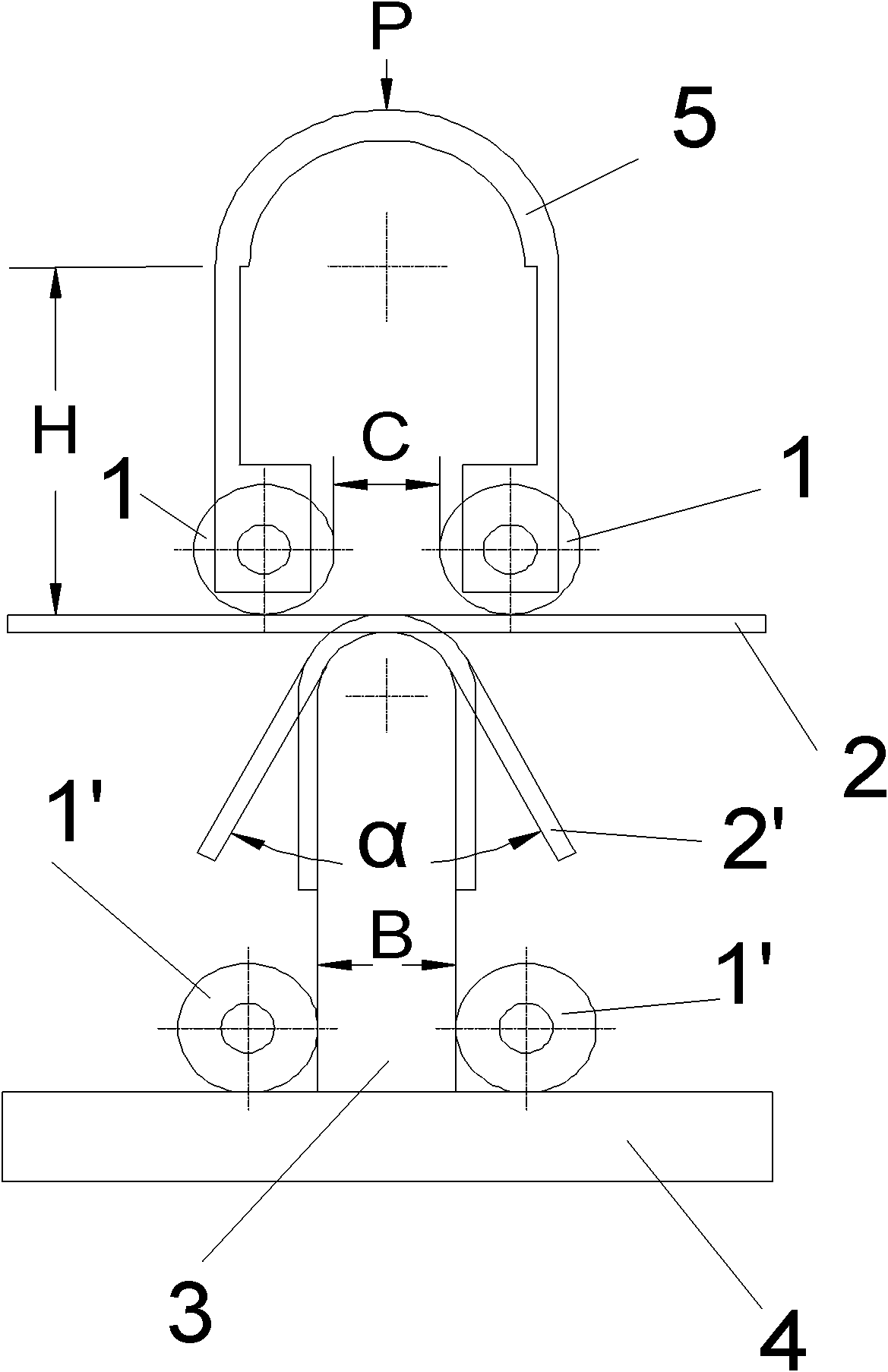
[0015] Such as figure 1 As shown, in the figure 1 is two guide wheels, which are installed at the lower end of the elastic sheet 5, 2 is a U-shaped thin strip to be tested, which is located at the lower end of the two guide wheels, there is an opening (C) between the two guide wheels, and 3 is a punch Head, located at the lower end of the guide wheel 1, 4 is a support plate, located at the lower end of the punch; the width of the opening (C) is smaller than the thickness B of the punch (3), so as to clamp the measured thin strip forming part 2' during stamping, The upper end of the punch is semicircular and has a smooth surface. The height H should be such that the guide wheel rushes to the position of guide wheel 1' in the figure, so that the guide wheel is away from the lower foot of part 2'.

[0016] T10 steel is selected as the elastic sheet 5 with a thickness of 2mm and a width of 15mm. H is 80mm, the tested strip 2 is 0.2×1.6 tin-coated copper strip, the substrate coppe...

Embodiment 2

[0018] The situation is basically the same as in Example 1, except that the 0.2mm thick tin-coated copper strips that have been generally annealed and fully annealed are used as the tested strips, and the obtained α values ​​are 15° and 10° respectively.

Embodiment 3

[0020] The situation is basically the same as in Example 1, except that the 0.5mm thick tin-coated copper strips that have been generally annealed and fully annealed are used as the tested strips, and the obtained α values ​​are 15° and 10° respectively.

[0021] The application of the present invention on the tin-coated copper strip on the photovoltaic cell board is of great significance! The supplier of tin-coated copper strip can mark the springback angle α value, and the application company can also use this device to test its softness and hardness. It is no longer necessary to scrape off the coating and then use a hardness tester to identify soft and hard. That is to say, the larger the rebound angle α value of the tin-coated copper strip, the harder it is, and the higher the debris rate in the process of welding silicon cells, and vice versa.


PUM


Abstract

The invention relates to the technical field of test, and particularly relates to a hardness test technology and equipment thereof. A manufacture device of a thin strip rebound body in the invention is characterized in that the device is provided with a U-shaped elastic piece (5), two legs at the lower end of the elastic piece (5) are provided with two guide wheels (1), an opening (C) is formed between the two guide wheels (1), a punch (3) is vertically arranged on the lower ends of the guide wheels (1), a supporting plate (4) is arranged at the lower end of the punch (3), and a thin strip to be tested (2) is located between the two guide wheels (1) and the punch (3); the width of the opening (C) is smaller than the thickness B of the punch (3), so that the thin strip to be tested (2) is clamped in the punching process so as to form a piece (2'); the upper end of the punch (3) is semicircular and has smooth surface, and the height H of the punch needs to meet a condition that the guide wheels (1) can be punched to the position of guide wheels (1') in an illustration, so that the guide wheels can be separated from the lower leg of the piece (2'). The manufacture device of the thin strip rebound body can be used for testing the harness of materials, and has the advantages of saving labor force, saving time and saving investment.

Description

technical field [0001] The invention relates to the technical field of testing, in particular to hardness testing technology and equipment. Background technique [0002] In the prior art, hardness testers are mainly used to measure the hardness of materials, including Brinell hardness testers and Vickers hardness testers. Measuring the hardness of materials with a hardness tester is complex and expensive. [0003] In addition, for the interconnection strips (interconnection strips in tin-coated copper strips) used in photovoltaic panels, the surface of the copper strips is very soft when tin alloy is coated, so there is no need to measure the softness and hardness, but the hardness of the core copper must be measured. The tin alloy coating had to be removed first, a laborious and time-consuming process that also required chemical expertise. Due to the high hardness of the interconnection strip, the fragmentation rate of the silicon cell is large during welding, so manufact...

Claims


Application Information

Patent Timeline
Patent Type & Authority Applications(China)
IPC IPC(8): G01N3/02G01N3/40
Inventor 刘雅洲李志平刘璐刘颖绚刘艳绚
Owner 昆明三利特科技有限责任公司
Why Eureka
Try Eureka