Image encoding device, image encoding method and program thereof, and image decoding device, image decoding method and program thereof

An image encoding and image decoding technology, applied in the field of image decoding methods and programs, can solve problems such as inability to recover, and achieve the effect of efficient reception or read-in

Inactive Publication Date: 2011-11-30
VICTOR CO OF JAPAN LTD
View PDF3 Cites 35 Cited by
  • Summary
  • Abstract
  • Description
  • Claims
  • Application Information

AI Technical Summary

Problems solved by technology

As long as the main image and the disparity vector are used, an image similar to the sub-image can be restored, but the prediction residual signal must be transmitted or recorded because the sub-image information that does not exist in the main image, such as the shadow part of the object, cannot be restored.

Method used


Image

  • Image encoding device, image encoding method and program thereof, and image decoding device, image decoding method and program thereof
  • Image encoding device, image encoding method and program thereof, and image decoding device, image decoding method and program thereof
  • Image encoding device, image encoding method and program thereof, and image decoding device, image decoding method and program thereof

Examples


Embodiment approach 1

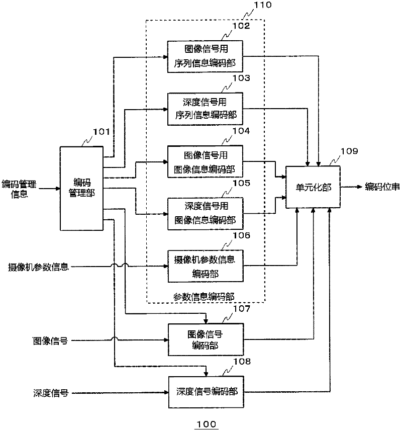
[0069] figure 1 It is a block diagram showing the configuration of the image encoding device 100 according to the first embodiment. The image encoding device 100 according to Embodiment 1 includes an encoding management unit 101 , a parameter information encoding unit 110 , an image signal encoding unit 107 , and a depth information encoding unit (more specifically, a depth signal encoding unit 108 ). The parameter information encoding unit 110 includes an image signal sequence information encoding unit 102 , a depth signal sequence information encoding unit 103 , an image signal image information encoding unit 104 , a depth signal image information encoding unit 105 , and a camera parameter information encoding unit 106 .

[0070]These configurations can be realized by CPU, memory, and other LSIs of any computer in terms of hardware, and can be realized by programs loaded into the memory in terms of software, but here the functional blocks realized by their cooperation are de...

Embodiment approach 2

[0281] Next, an image decoding device 300 for decoding encoded data encoded by the image encoding devices 100 and 100a according to Embodiment 1 will be described.

[0282] Figure 21 It is a block diagram showing the configuration of the image decoding device 300 according to Embodiment 2 of the present invention. The image decoding device 300 according to Embodiment 2 includes a decomposition unit 301, a decoding management unit 302, a parameter information decoding unit 320, an image signal decoding unit 307, a depth information decoding unit (more specifically, a depth signal decoding unit 309), and a decoded image Buffer 310 . The parameter information decoding unit 320 includes a base-view image signal sequence information decoding unit 303 , a sequence information decoding unit 304 including MVC extension information, an image information decoding unit 305 , and a supplemental enhancement information decoding unit 306 .

[0283] The decomposer 301 decomposes the coded...

Embodiment approach 3

[0365] Next, an image encoding device according to Embodiment 3 of the present invention will be described. The image coding device according to the third embodiment judges the viewpoint of the image signal and the depth signal to be coded based on the content or the content of the scene, and encodes only the image signal and the depth signal of the necessary viewpoint based on the judgment. In this respect, it is different from the image encoding device in Embodiment 1. Other than that, it is the same as the image coding device according to Embodiment 1, so description of the same parts will be omitted.

[0366] Figure 25 It is a block diagram showing the configuration of the image coding device 400 according to the third embodiment. exist Figure 25 in, right with figure 2 The same constituent blocks are denoted by the same reference numerals. The image coding device 400 according to the third embodiment has a configuration in which a determination unit 120 and switch...


PUM


Abstract

An image signal encoding unit 107 generates image encoded data by encoding a plurality of images from multiple viewpoints different from each other. A depth information encoding unit (e.g., a depth signal encoding unit 108) generates depth information encoded data by encoding depth information that indicates the depth of a specific space from at least one viewpoint. A unitization unit 109 generates an encoded stream including the image encoded data and depth information encoded data, which are respectively generated by the image signal encoding unit 107 and the depth information encoding unit.

Description

technical field [0001] The present invention relates to an image encoding device for encoding images captured from a plurality of different viewpoints, an image encoding method, and a program thereof, and an image for decoding encoded image data encoded with images captured from a plurality of different viewpoints A decoding device, an image decoding method and a program thereof. Background technique [0002] In recent years, applications using images from multiple viewpoints have become widespread. As one of the applications, there is a binocular stereoscopic television. In binocular stereoscopic television, images for the left eye and images for the right eye captured by two cameras from two different directions are generated and displayed on the same screen to allow people to see stereoscopic images. In this case, the image for the left eye and the image for the right eye are separately transmitted or recorded as independent images. In this case, approximately twice th...

Claims


Application Information

Patent Timeline
Patent Type & Authority Applications(China)
IPC IPC(8): H04N7/26
CPCH04N19/00781H04N7/50H04N19/00769H04N7/26946H04N19/00884H04N19/597H04N19/61H04N19/70
Inventor 中村博哉上田基晴
Owner VICTOR CO OF JAPAN LTD
Why Eureka
Try Eureka