Apparatus and method for treating process exhaust gas

A waste gas treatment device and waste gas treatment technology, which are applied in separation methods, chemical instruments and methods, and dispersed particle separation to achieve the effects of slowing down corrosion, reducing corrosion, and being convenient for replacement.

Active Publication Date: 2013-06-19
MACRONIX INT CO LTD
View PDF5 Cites 0 Cited by
  • Summary
  • Abstract
  • Description
  • Claims
  • Application Information

AI Technical Summary

Problems solved by technology

However, the cost required to replace the funnel is considerable

Method used


Image

  • Apparatus and method for treating process exhaust gas
  • Apparatus and method for treating process exhaust gas
  • Apparatus and method for treating process exhaust gas

Examples


Embodiment Construction

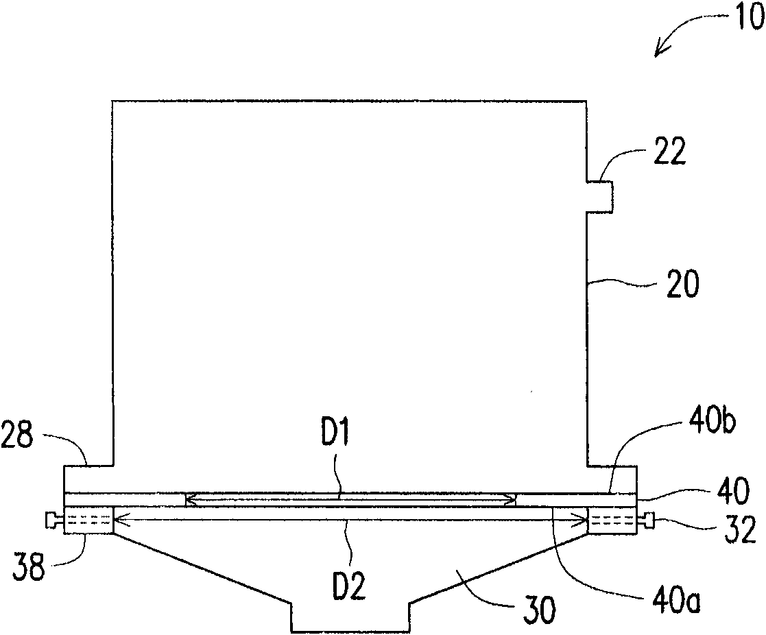
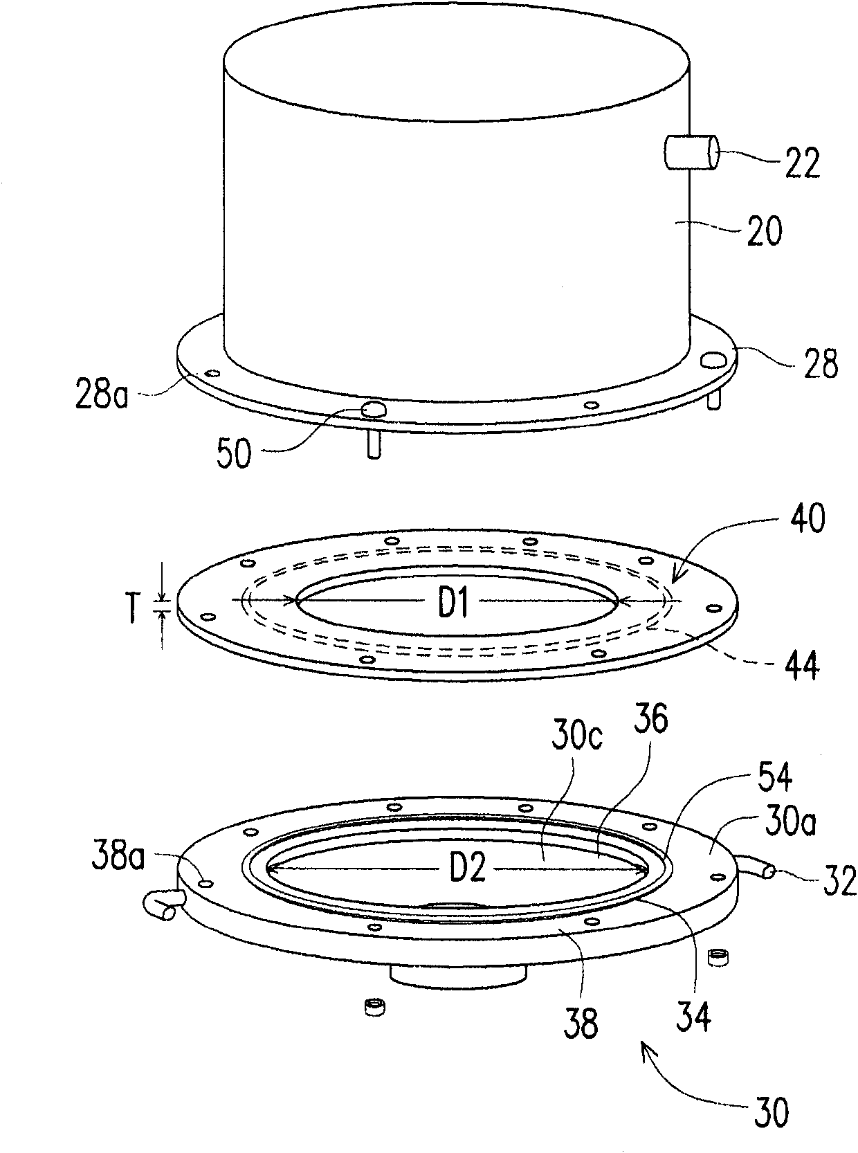
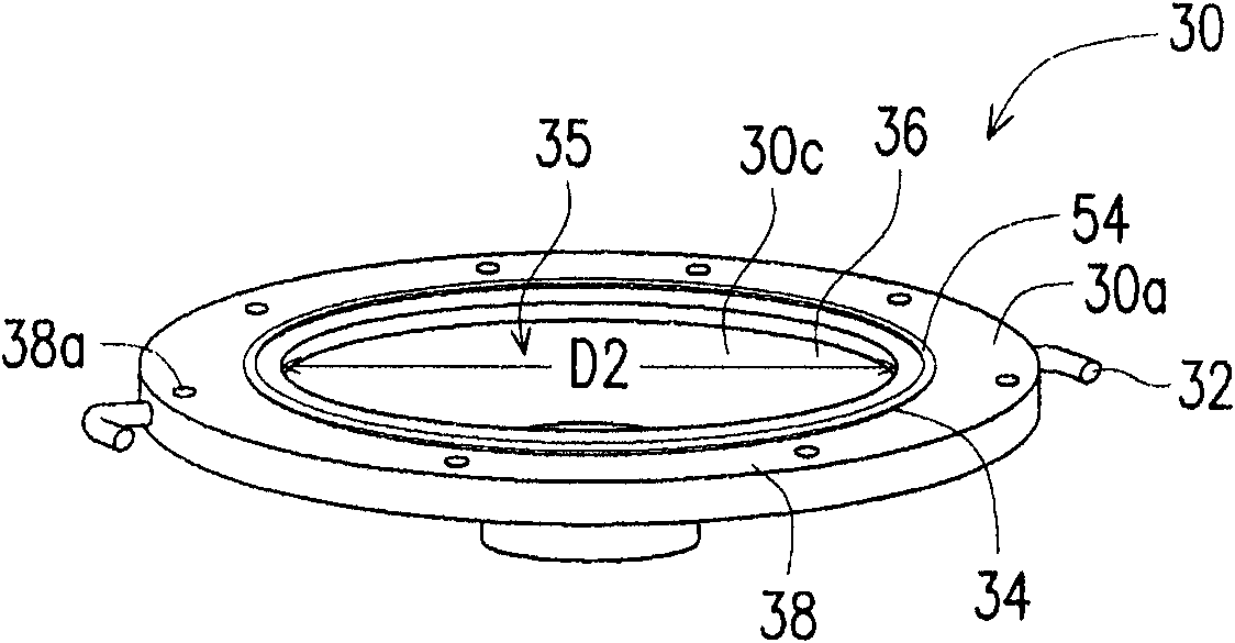
[0049] figure 1 A schematic cross-sectional view of a process waste gas treatment device according to an embodiment of the present invention is shown. figure 2 A schematic disassembly diagram of a process waste gas treatment device according to an embodiment of the present invention is shown. image 3 A schematic diagram showing the funnel of the process waste gas treatment unit. Figure 4 A schematic diagram showing the cap ring on the funnel.

[0050] Please refer to figure 1 , the process waste gas treatment device 10 includes a cavity 20 , a funnel 30 and a top cover ring 40 . The cavity 20 has at least one waste gas inlet 22, which can introduce the process waste gas generated by the process equipment. In the drawings, the exhaust gas inlet 22 is arranged on the side wall of the cavity 20 , but not limited thereto, the exhaust gas inlet 22 can also be arranged at a suitable position according to actual needs, such as above the cavity 20 . The cavity 20 may have a pl...


PUM


Abstract

The invention provides an apparatus for treating process exhaust gas, and the apparatus comprises a cavity and a funnel top cover ring. A funnel is provided below the cavity and has at least one filling hole which is arranged close to the cavity.

Description

technical field [0001] The invention relates to a process waste gas treatment device and a process waste gas treatment method. Background technique [0002] General factories often produce waste gas during the production process. Most of these exhaust gases are harmful to the environment and need to be treated before being discharged into the general environment. Exhaust gas from existing process machines, after being extracted from the process reaction chamber, will first pass through the exhaust gas treatment device before further treatment. [0003] High temperature combustion is one of the most common methods of waste gas treatment. The exhaust gas treatment device used in high-temperature combustion is mainly composed of an exhaust gas treatment chamber and a funnel. The process waste gas is passed into the treatment chamber for waste gas decomposition, reaction and other treatment. The solid powdery condensate produced after the treatment is usually deposited on the...

Claims


Application Information

Patent Timeline
Patent Type & Authority Patents(China)
IPC IPC(8): B01D53/34
Inventor 谢正益
Owner MACRONIX INT CO LTD
Why Eureka
Try Eureka