Neighborhood brightness matching for uniformity of tiled displays

A splicing display and brightness technology, which is applied to static indicators, cathode ray tube indicators, image reproducers using projection devices, etc., can solve problems such as uneven brightness of splicing display systems

Inactive Publication Date: 2011-12-07
普雷斯姆股份有限公司
View PDF3 Cites 40 Cited by
  • Summary
  • Abstract
  • Description
  • Claims
  • Application Information

AI Technical Summary

Problems solved by technology

[0004] However, since the brightness of individual tiles may decrease over time, for example due to changes in light source performance, initial calibration cannot always avoid brightness non-uniformity in the video wall over the lifetime of the system

Method used


Image

  • Neighborhood brightness matching for uniformity of tiled displays
  • Neighborhood brightness matching for uniformity of tiled displays
  • Neighborhood brightness matching for uniformity of tiled displays

Examples


Embodiment Construction

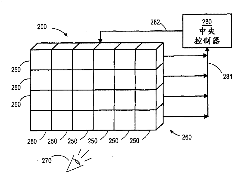
[0020] figure 1 It is a schematic perspective view of a video wall 200 that can benefit from embodiments of the present invention. Video wall system 200 includes a plurality of tiles 250 positioned to form a single display screen 260 for a viewer 270 . Each tile 250 is a light-based electronic display device, such as a laser phosphor display (LPD), light emitting diode (LED) digital light processor (DLP), or LED liquid crystal display (LCD) device, and each tile configured to work with other tiles 250 to produce a single, associated image for a viewer 270 . Each tile 250 also includes an illuminance detector (not shown for clarity) for dynamically monitoring the output intensity of the light source or light sources in the tile 250. figure 1 shown in ). Illuminance is a photometric measurement of the luminous intensity per unit area of ​​light propagation in a given direction. The tiled display system 200 includes a central controller 280 configured to receive illuminance d...


PUM


Abstract

Brightness between the individual tiles of a tiled display system 260 is matched for improved uniformity and overall brightness of images produced by the display system. Regions 253 of the display system adjacent to a tile 251 with low brightness performance are incremented in brightness from the brightness level of the low brightness tile to the brightness level of higher brightness tiles 254. By incrementing the brightness of such regions according to embodiments of the invention, perceived brightness uniformity of images produced by the tiled display system is maintained while maximizing the overall brightness of the display device. The regions used to increment brightness may be as large as an entire tile or as small as a single pixel element. A luminance detector sends luminance information to a control unit which determines if the brightness of a first tile is below a threshold value, if so the brightness of adjacent tiles is adjusted.

Description

technical field [0001] Embodiments of the present invention relate generally to tiled display screens, and more particularly to brightness matching systems and methods that improve the uniformity and brightness of such display screens. Background technique [0002] Electronic display systems are commonly used to display information from computers and other sources. Typical display system sizes range from small displays for mobile devices to very large displays such as tiled displays used to display images to thousands of viewers simultaneously. Video walls typically consist of multiple smaller individual display devices, or "tiles," that are finely arranged when combined to provide a seamless and uniform appearance. [0003] Since the human eye can easily detect small differences in the brightness uniformity of the displayed image, the use of multiple display devices in a video wall system can cause problems when the output of one or more independent tiles does not closely ...

Claims


Application Information

Patent Timeline
Patent Type & Authority Applications(China)
IPC IPC(8): G09G5/14G09G5/10
CPCG09G5/10G09F9/33G09F9/35G09G3/34G09F9/3026G09F9/30G09G2320/0233H04N9/31G09G5/00G06F3/1446G09G5/14
Inventor A・玛哈加
Owner 普雷斯姆股份有限公司
Why Eureka
Try Eureka