Methods and apparatuses of eye adaptation support

Inactive Publication Date: 2013-08-01
T C VIEW
View PDF4 Cites 23 Cited by
  • Summary
  • Abstract
  • Description
  • Claims
  • Application Information

AI Technical Summary

Benefits of technology

The present invention provides a device for reducing the brightness level of a portion of a display area of an imaging unit. It includes a gaze tracking unit, a controllable transparency panel, and a controller. The controller instructs the controllable transparency panel to change the brightness reduction pattern according to the eye gazing direction in real time so that the location of the original display brightness portion is correlated with the location of at least one fovea of the observer in real time. The calculating is performed according to a weight function so that areas of the brightness reduction pattern which are closer to the original display brightness portion are more transparent than areas which are more remote from the original display brightness portion, resulting gradual decrease of brightness from the center of field of view of the retina toward other retinal portions. The device can reduce the brightness levels of previous locations of the original display brightness portion.

Problems solved by technology

However, it takes approximately five minutes for the eye to adapt to bright sunlight from darkness.
Rods are more sensitive to light and take longer to fully adapt to the change in light.

Method used


Image

  • Methods and apparatuses of eye adaptation support
  • Methods and apparatuses of eye adaptation support
  • Methods and apparatuses of eye adaptation support

Examples


Embodiment Construction

[0042]The present invention, in some embodiments thereof, relates to eyesight enhancement and, more particularly, but not exclusively, to methods and systems of providing eye adaptation support for viewing imaging apparatuses.

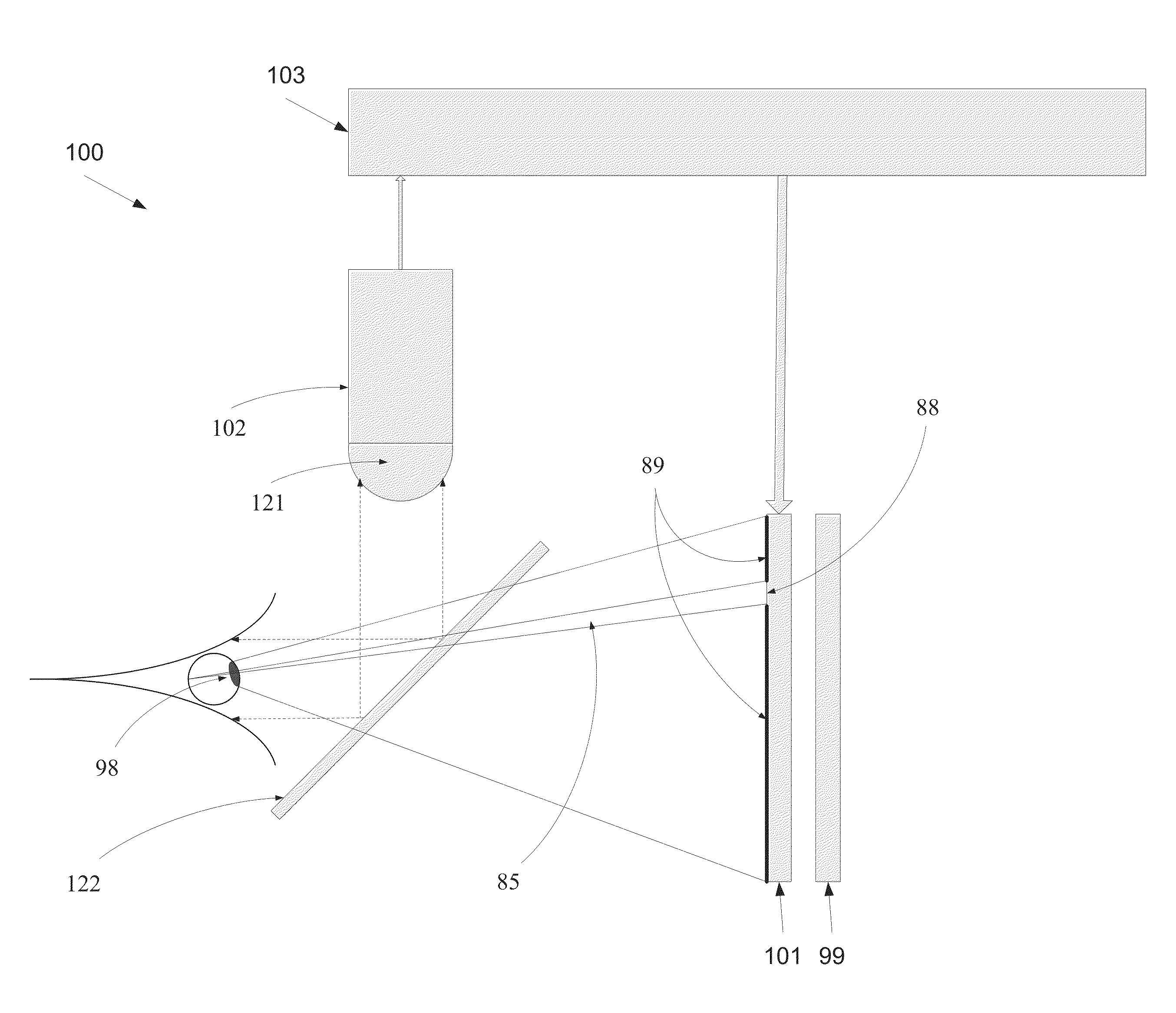
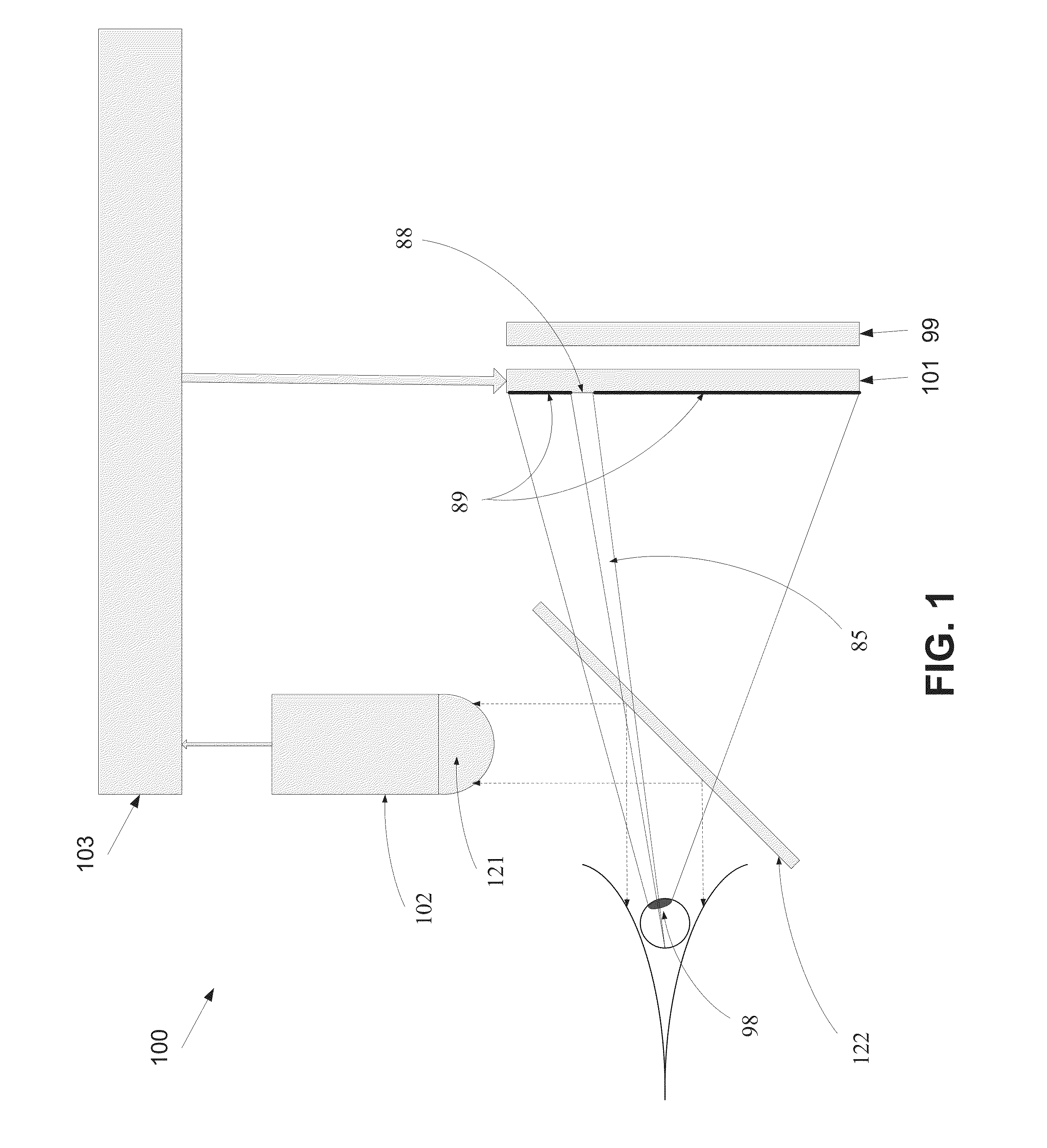
[0043]According to some embodiments of the present invention, there are provided methods and devices for reducing the brightness of a portion of an image projected from a display area of an imaging apparatus, such as a night vision apparatus, while the brightness level of another portion remains unchanged or substantially unchanged. The device optionally includes a gaze tracking unit, such as a pupil tracking unit, which is to adapted to detect eye gazing direction of an observer, for example the coordinates of a pupil and / or an eye movement vector. The device further includes a controllable transparency panel, such as a spatial light transparency modulator or a transparent screen, which is adapted to be mounted in front of the display area of the imaging appar...


PUM


Abstract

A device for reducing the brightness level of a portion of a display area of an imaging unit. The device comprises a gaze tracking unit adapted to assess eye gazing direction of an observer, a controllable transparency panel adapted to be mounted in front of a display area of an imaging unit and to display a changeable brightness reduction pattern having a original display brightness portion and a darkening portion therearound, and a controller which instructs the controllable transparency panel to change the brightness reduction pattern according to the eye gazing direction in real time so that the location of the original display brightness portion being correlated with the location of at least one fovea of the observer in real time.

Description

FIELD AND BACKGROUND OF THE INVENTION[0001]The present invention, in some embodiments thereof, relates to eyesight enhancement and, more particularly, but not exclusively, to methods and systems of providing eye adaptation support for viewing imaging apparatuses.[0002]The human eye can function from very dark to very bright levels of light; its sensing capabilities reach across nine orders of magnitude. This means that the brightest and the darkest light signal that the eye can sense are a factor of roughly 1,000,000,000 apart. However, in any given moment of time, the eye can only sense a contrast ratio of one thousand.[0003]A human observer sees colors, distinguishes among slight details or reads, only at certain very narrow viewing angle which is referred to as the Fovea. The central fovea, also known as the foveola, is about 0.2 mm in diameter—where only cone photoreceptors are present and there are virtually no rods. The central fovea consists of very compact cones, thinner and...

Claims


Application Information

Patent Timeline
IPC IPC(8): G09G5/10
CPCG02B5/003G09G5/10G02B27/0093G02B23/12G09G2354/00G09G2320/0261G09G3/001
Inventor TAMIR, ZEEV
Owner T C VIEW
Why Eureka
Try Eureka