Reducing sparkle artifacts with low brightness processing

a technology of low brightness and processing, applied in the field of video systems, can solve the problems of unsatisfactory flicker in the displayed picture, undesired bright edges of objects, green sparkle attributed to declination errors is a new kind of problem, etc., and achieves the effect of high brightness level, high definition detail, and no degrading the high definition sharpness of the resulting display

Inactive Publication Date: 2002-09-12
INTERDIGITAL CE PATENT HLDG
View PDF14 Cites 10 Cited by
  • Summary
  • Abstract
  • Description
  • Claims
  • Application Information

AI Technical Summary

Benefits of technology

0014] The inventive arrangements taught herein solve the problem of sparkle in LCOS imagers attributed to declination without degrading the high definition sharpness of the resulting display. Moreover, and absent an opportunity to address the problem by modification of LCOS imagers, the inventive arrangements advantageously solve the sparkle problem by modifying the video signal to be displayed, thus advantageously presenting a solution that can be applied to all LCOS imagers. The video signal can be, for example, an input luminance signal or a video drive signal. The video signal is signal processed in such a way that higher brightness level information is advantageously unchanged, thus retaining high definition detail. At the same time, the lower brightness levels of the luminance component that directly result in sparkle are filtered and limited in such a way that the sparkle is advantageously prevented altogether, or at least, is reduced to a level that cannot be perceived by a viewer. The signal processing or filtering of the lower brightness level information advantageously does not adversely affect the detail of the high definition display. Moreover, the signal filtering and limiting advantageously can be adjusted or calibrated in accordance with the non-linearity of any gamma table, and thus, can be used with and adjustably fine tuned for different LCOS imagers in different video systems.

Problems solved by technology

Such variation of the brightness can cause an undesirable flicker in the displayed picture.
This orthogonal field produces a brighter than desired pixel, which in turn can produce undesired bright edges on objects.
However, the green sparkle is the most evident when the problem occurs.
LCOS imaging is a new technology and green sparkle attributed to declination errors is a new kind of problem.
Various proposed solutions process the entire luminance component of the picture, and in so doing, degrade the quality of the entire picture.
Picture detail and sharpness simply cannot be sacrificed in that fashion.
However, in an emerging technology such as LCOS, there simply isn't an opportunity for parties other than the manufacturer of the LCOS imagers to fix the problem in the imagers.
Moreover, there is no indication that an imager-based solution would be applicable to all LCOS imagers.

Method used


Image

  • Reducing sparkle artifacts with low brightness processing
  • Reducing sparkle artifacts with low brightness processing
  • Reducing sparkle artifacts with low brightness processing

Examples


Embodiment Construction

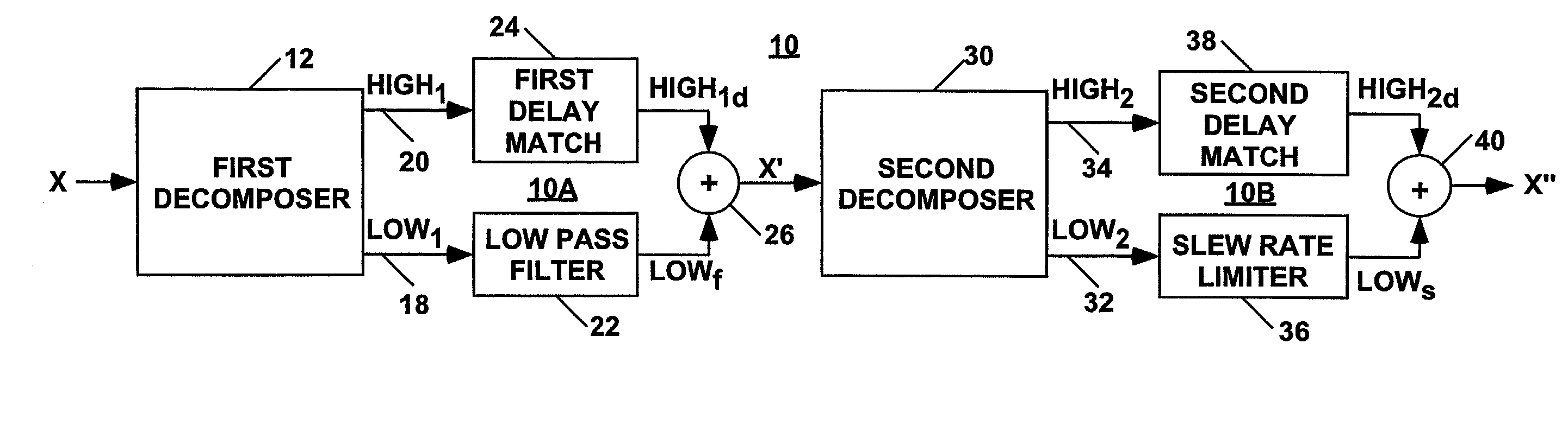
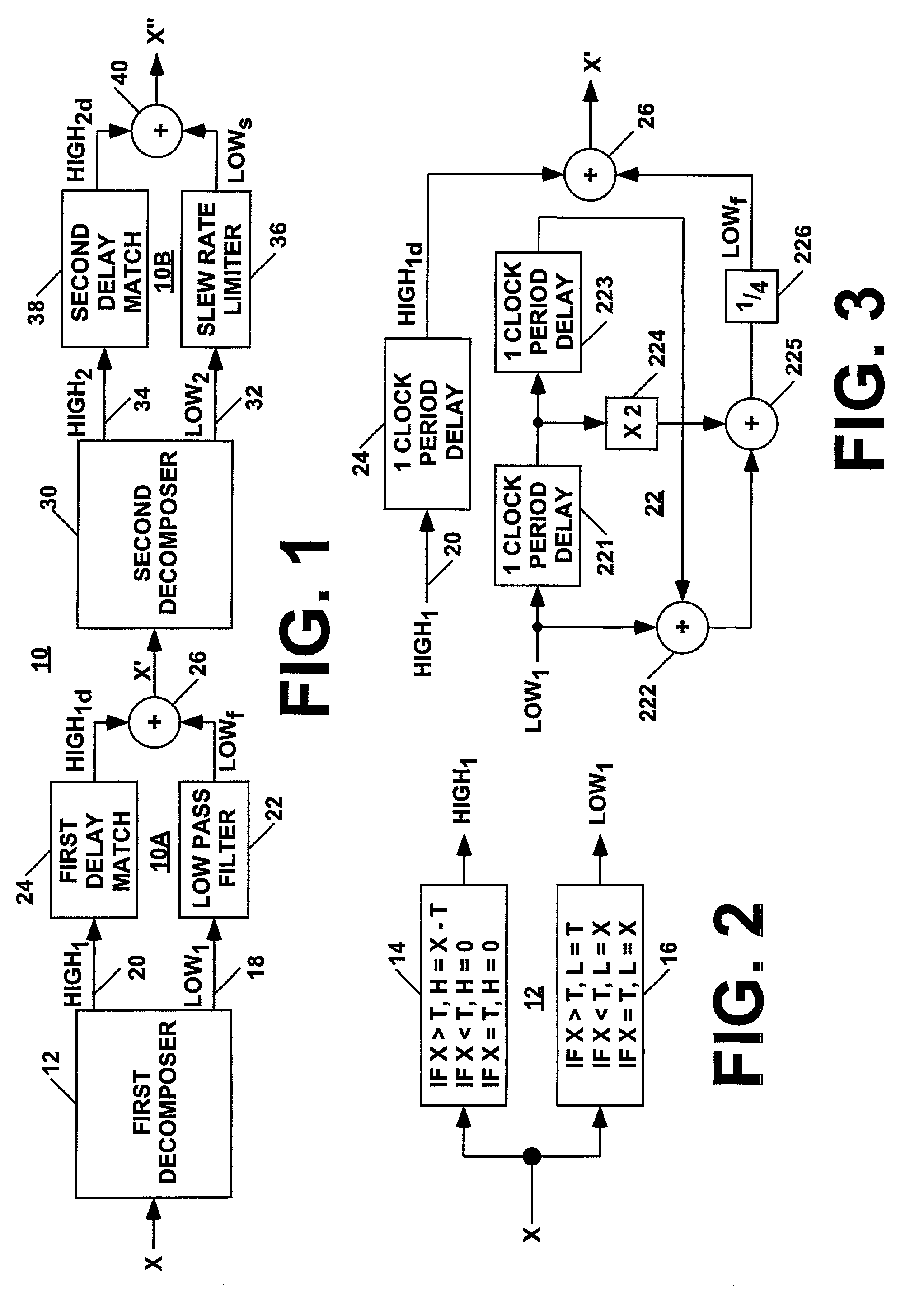
[0031] A circuit for reducing sparkle artifacts attributed to declination errors in liquid crystal video systems, for example LCOS video systems, is shown in FIG. 1 and generally denoted by reference numeral 10. The circuit 10 is a tandem processor, comprising a first stage 10A in which lower brightness levels are low pass filtered and a second stage 10B in which low pass filtered lower brightness levels are slew rate limited.

[0032] The first stage 10A comprises a first decomposer 12, a low pass filter 22, a delay match circuit 24 and an algebraic unit 26. An input video signal X, for example a luminance signal or a video drive signal, is modified by the circuit 10, and in response, an intermediate video signal X' is generated. The video signal is a digital signal, and the waveform is a succession of digital samples representing brightness levels. The brightness levels are measured, for example, in IRE values. The intermediate signal X' has a similar digital format. The first decomp...


PUM

PropertyMeasurementUnit
voltageaaaaaaaaaa
voltageaaaaaaaaaa
voltageaaaaaaaaaa

Abstract

A method for reducing sparkle artifacts in a liquid crystal imager, comprises the steps of: low pass filtering only a first lower brightness level signal component of a video signal; and, slew rate limiting only a second lower brightness level signal component of the video signal having the low pass filtered signal component, the video signal having the low pass filtered and the slew rate limited signal components being less likely to result in sparkle artifacts in the imager. Brightness thresholds for defining the lower brightness level signal components and slew rate limits can be selected in accordance with transitions between lower and higher level gain portions of a gamma table associated with the imager, for example an LCOS imager.

Description

BACKGROUND OF THE INVENTION[0001] 1. Field of the Invention[0002] This invention relates to the field of video systems utilizing a liquid crystal display (LCD), and in particular, to video systems utilizing normally white liquid crystal on silicon imagers.[0003] 2. Description of Related Art[0004] Liquid crystal on silicon (LCOS) can be thought of as one large liquid crystal formed on a silicon wafer. The silicon wafer is divided into an incremental array of tiny plate electrodes. A tiny incremental region of the liquid crystal is influenced by the electric field generated by each tiny plate and the common plate. Each such tiny plate and corresponding liquid crystal region are together referred to as a cell of the imager. Each cell corresponds to an individually controllable pixel. A common plate electrode is disposed on the other side of the liquid crystal. Each cell, or pixel, remains lighted with the same intensity until the input signal is changed, thus acting as a sample and ho...

Claims


Application Information

Patent Timeline
Patent Type & Authority Applications(United States)
IPC IPC(8): G02F1/13G09G3/36H04N5/20H04N5/21H04N5/66H04N9/30H04N9/64
CPCG09G3/3611G09G2320/0247G09G2320/0606G09G2320/0626H04N5/20H04N5/21H04N9/30H04N9/646G02F1/13
Inventor WILLIS, DONALD HENRYHAGUE, JOHN ALAN
Owner INTERDIGITAL CE PATENT HLDG
Why Eureka
Try Eureka