U-rib welding process of steel bridge deck

A steel bridge deck and welding process technology, applied in welding equipment, manufacturing tools, arc welding equipment, etc., can solve the problems of reduced welding efficiency and inability to achieve simultaneous welding

Inactive Publication Date: 2011-12-14
SHANGHAI ZHENHUA HEAVY IND
View PDF9 Cites 16 Cited by
  • Summary
  • Abstract
  • Description
  • Claims
  • Application Information

AI Technical Summary

Problems solved by technology

This kind of welding cannot achieve the goal of welding both sides o...

Method used


Image

  • U-rib welding process of steel bridge deck
  • U-rib welding process of steel bridge deck
  • U-rib welding process of steel bridge deck

Examples


Embodiment Construction

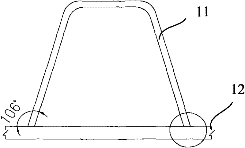
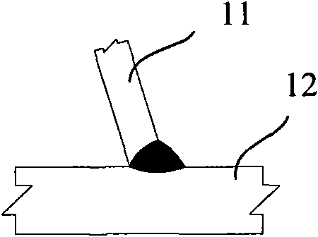
[0021] Figure 1A A schematic diagram showing the welding of steel bridge deck and U-rib. As shown in FIG. 1 , the two ends of the U rib 11 are placed at the welding position of the steel bridge deck 12 to wait for welding. The thickness of the U-rib used in this embodiment may be 12 mm or more, the thickness of the bottom plate may be 14-30 mm, and the angle between the U-rib and the bottom plate may be 106°. Typically, the welding requirement is that the weld penetration should exceed 80%. In addition, the workpiece material is ASTM A709M345.

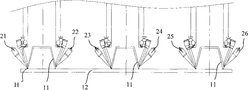
[0022] In the embodiment of the present invention, according to the requirements of AWS D1.5, the welding procedure qualification test and the mechanical property test of the selected welding material are carried out to determine the required mechanical properties of the welding material, thereby determining the appropriate welding process. In summary, the welding process adopts the method of solid core wire mixed gas bottoming and ...


PUM

PropertyMeasurementUnit
Diameteraaaaaaaaaa

Abstract

The invention relates to a U-rib welding process for a steel bridge deck, comprising the following steps. First, place the ends of the U-rib on the welded position of the steel bridge deck. Secondly, use the gas shielded welding head to perform gas shielded welding on the welding position in front, and at the same time use the submerged arc welding head to perform automatic submerged arc welding on the welding position. Therefore, on the premise that the thickness of the U rib plate reaches 12mm, the purpose of weld penetration rate of 80%-100% is realized.

Description

technical field [0001] The invention relates to a welding process in the manufacture of a steel bridge, in particular to a welding process between a steel bridge deck and a U rib. Background technique [0002] There are more and more bridges using steel as the main construction material for large bridges in the world today. Steel bridges have the advantages of high strength and high rigidity, and compared with concrete bridges, the beam height and self-weight can be reduced. In manufacturing, steel bridges are generally manufactured in factories and spliced ​​on site, which has the advantages of short construction period, convenient processing and not affected by seasons. [0003] In terms of manufacturing, the welding of steel bridges, especially the welding of large-scale steel bridge decks and U-ribs of steel bridges has always been the focus of steel bridge production. How to ensure the quality of the weld seam, welding efficiency and the penetration rate of the weld s...

Claims


Application Information

Patent Timeline
IPC IPC(8): B23K9/00B23K9/18B23K9/16B23K9/095B23K9/235B23K33/00
Inventor 沈大明黄巍
Owner SHANGHAI ZHENHUA HEAVY IND
Why Eureka
Try Eureka