Rod type escape device

An escape device and pressure rod type technology, which is applied in the field of safety doors, can solve problems such as impossibility, and achieve the effect of saving replacement costs

Active Publication Date: 2011-12-14
YUYAO DAERMAN HARDWARE
View PDF6 Cites 4 Cited by
  • Summary
  • Abstract
  • Description
  • Claims
  • Application Information

AI Technical Summary

Problems solved by technology

[0003] The purpose of the present invention is to solve the problem that the existing common locks cannot open the door quickly with one action in the event of an emergency, and provide a reasonable structural design, with a

Method used


Image

  • Rod type escape device
  • Rod type escape device
  • Rod type escape device

Examples


Embodiment Construction

[0026] The technical solutions of the present invention will be further specifically described below through the embodiments and in conjunction with the accompanying drawings.

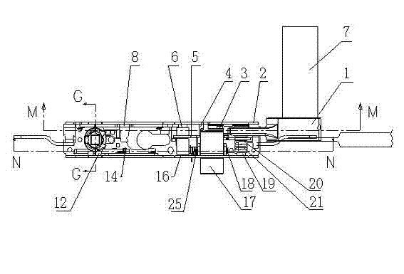
[0027] see Figure 8 , a pressure bar type escape device in this embodiment, comprising a main lock body A, an upper lock body B arranged above the main lock body A, a lower lock body C arranged below the main lock body A, the main lock body A and the lower lock body The lock bodies C are connected by the lower connecting rod 24 and the pipe 11, and a depression bar E is vertically arranged with the handle 1, and the depression bar E is connected with the secondary lock body D parallel to the main lock body A.

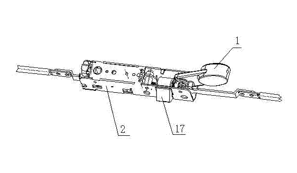
[0028] Such as figure 1 , figure 2Shown, main lock body is provided with the base 2 of channel steel type, and the head of main dead bolt 17 cooperates with the hole gap that the side of base 2 channel steel type offers, and one end of base is provided with handle 1, and handle 1 There is a...


PUM


Abstract

Relating to the technical field of safety doors, the invention especially relates to a compression bar type escape device, with which a safety door can be opened rapidly by pushing the compression bar, and provides a solution to the problem that present common locksets cannot open the door rapidly through an act when emergencies take place. The device comprises a main lock body, an upper lock body and a lower lock body of the same structure. The device is characterized in that the main lock body is provided with a pedestal and a main lock bolt. A handle is arranged at one end of the pedestal and is connected to the pedestal through a handle shaft, which is provided with a rear rotation plate. One end of the rear rotation plate and one surface of the main lock bolt are positioned on the working face of a front moving plate. A roller is equipped between the main lock bolt tail and the working face of the front moving plate, and the central section of the main lock bolt is provided with a lock bolt shaft. The front moving plate is equipped with a gib matching a moving plate, one end of which is connected to an upper connecting bar. A direction control column is provided at one end of the pedestal having the moving plate. The direction control column is connected to a beak plate that is in connection with the moving plate and is provided with a beak plate pin.

Description

technical field [0001] The invention relates to the technical field of safety doors, in particular to a pressure rod-type escape device that can quickly open a safety door by pushing a pressure rod. Background technique [0002] When an emergency occurs, it is extremely important to evacuate the people in the venue in an emergency. The escape device for the safety door is designed for this purpose. The escape device is commonly known as a push rod lock and is installed at the emergency exit door of the safety door. Fire, explosion, etc., can quickly evacuate the crowd and minimize casualties. Existing safe escape door technology forms are various, and structure is different. Such as patent publication number is CN101131057 a kind of door lock that is used for fire safety door, is provided with the locating plate that can lock square tongue drag plate in the lock housing, is also provided with runner assembly, driving lever in the lock housing, runner assembly and dial The ...

Claims


Application Information

Patent Timeline
IPC IPC(8): E05C9/08E05B3/00E06B5/00
Inventor 孙晓波林维华
Owner YUYAO DAERMAN HARDWARE
Why Eureka
Try Eureka