An experimental device and method for simulating the flow of molten iron in the hearth bottom of a blast furnace

An experimental device, blast furnace technology, which is applied in fluid dynamics tests, blast furnaces, measuring devices, etc., can solve problems such as large workload and experimental cost, difficulty in analyzing the reasons, and inability to cite and verify each other between results. The effect of material consumption and labor intensity, saving experimental costs, and saving scientific research costs

Inactive Publication Date: 2011-12-14
LAIWU IRON & STEEL GRP
View PDF4 Cites 9 Cited by
  • Summary
  • Abstract
  • Description
  • Claims
  • Application Information

AI Technical Summary

Problems solved by technology

The pressure inside the hearth is as high as 3 to 4 atmospheres, and the entire production process is fully enclosed, so the outside world can hardly directly observe the internal production conditions. When there is an abnormality in the hearth bottom of the blast furnace, it is difficult to analyze the cause, which brings great difficulties to metallurgical work. Analyzing problems, solving problems and causing difficulties
[0004] Domestically, there are few reports on the experimental research under the multi-parameter condition of the hearth bottom of the blast furnace, and no unified experimental scheme and experimental standard have been proposed, mainly because there are many factors involved in the flow state of molten iron in the hearth bottom of the blast furnace, which requires more Only a set of experimental devices or multiple experimental methods can be used for research, and the workload and experimental cost are relatively large, which is not conducive to the comprehensive research work of scientific researchers
In foreign countries, there are different opinions on the research on the physical model of the flow state of molten iron in the hearth bottom of the blast furnace. The physical model is designed according to the fields and problems of their own concern. In the process of designing the physical model, different assumptions are made and different influencing factors are ignored. So far, there is no uniform experimental method and specification, and the results obtained from different experiments cannot be mutually cited and confirmed, resulting in a large amount of repeated research and waste of resources

Method used


Image

  • An experimental device and method for simulating the flow of molten iron in the hearth bottom of a blast furnace
  • An experimental device and method for simulating the flow of molten iron in the hearth bottom of a blast furnace
  • An experimental device and method for simulating the flow of molten iron in the hearth bottom of a blast furnace

Examples


Embodiment 1

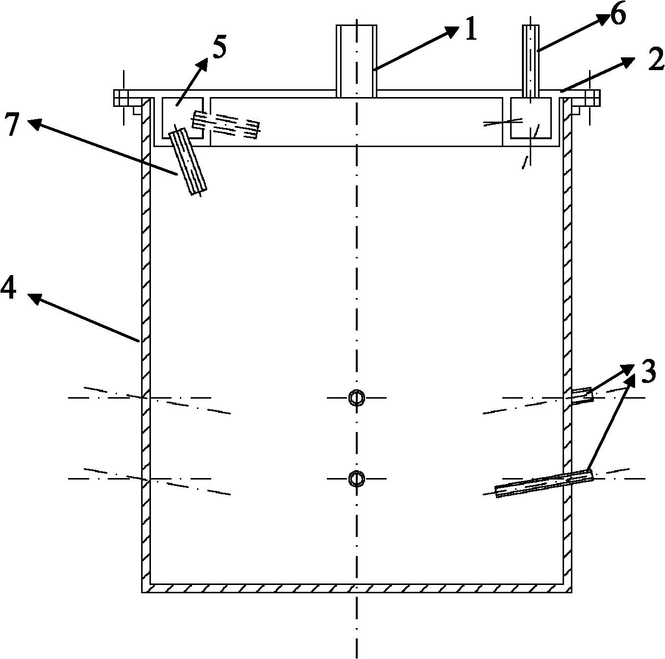
[0049] An experimental device for simulating the flow of molten iron at the hearth bottom of a blast furnace, comprising a cylindrical transparent container, a sealing cover, an air release hole, a cold air surrounding pipe and a water outlet, and the sealing cover is covered on the upper end of the cylindrical transparent container , the diameter of the sealing cover is adapted to the inner diameter of the cylindrical transparent container; the air release hole is arranged on the sealing cover; there is a cold air surrounding pipe on the lower surface of the sealing cover, and the surrounding diameter of the cold air surrounding pipe is the same as The inner diameter of the cylindrical transparent container is compatible; a cold air inlet is provided on the upper surface of the sealing cover, and the cold air inlet is connected with the cold air surrounding pipe; a plurality of air outlets are evenly arranged on the cold air surrounding pipe, and the air outlets are facing the ...

Embodiment 2

[0056] Utilize the experimental device described in embodiment 1 to simulate the method for molten iron flow state at the hearth hearth bottom of a blast furnace, the steps are as follows:

[0057] 1) Put the simulated dead material column into a cylindrical transparent container, and adjust the maximum diameter of the simulated dead material column to 400-450mm;

[0058] 2) Fill water into the cylindrical transparent container through the air release hole. When the water injection height reaches 300mm, open the lower water outlet, adjust the water injection flow rate, keep the liquid level constant at 300mm, adjust the floating height of the simulated dead material column, and make the simulated dead material The bottom of the material column is 100mm from the bottom of the container;

[0059] 3) Turn on the laser Doppler velocimeter, adjust the measuring position so that the lens of the laser Doppler velocimeter is positioned at the level of the upper water discharge hole, a...

Embodiment 3

[0065] As in the method described in Example 2, the difference is that the step 1) adjusts the maximum diameter of the simulated dead material column to 300-350 mm.


PUM

PropertyMeasurementUnit
diameteraaaaaaaaaa
sizeaaaaaaaaaa
angleaaaaaaaaaa

Abstract

The invention relates to a test device and a test method for simulating molten iron flow at furnace bottom of a blast-furnace hearth. The test device comprises a cylindrical transparent container, a sealing cover, an air scattering hole, a cold air bustle pipe and water discharging ports, wherein the sealing cover is covered at the upper end of the cylindrical transparent container; the diameter of the sealing cover is matched with the inner diameter of the cylindrical transparent container; the air scattering hole is formed on the sealing cover; the cold air bustle pipe is arranged on the lower surface of the sealing cover; an encircling diameter of the cold air bustle pipe is matched with the inner diameter of the cylindrical transparent container; a cold air inlet is formed on the upper surface of the sealing cover; the cold air inlet is communicated with the cold air bustle pipe; a plurality of air outlets are uniformly formed on the cold air bustle pipe; the air outlets are facedto the interior of the cylindrical transparent container; and two water discharging ports are formed on the cylindrical transparent container. The test device provided by the invention has the advantages that the flow status at the furnace bottom of the blast-furnace hearth which cannot be observed under normal production condition can be directly reflected by the test device, the flow status at the furnace bottom of the blast-furnace hearth can be conveniently and comprehensively researched, the material consumption and the labor intensity are reduced and the test cost is saved.

Description

technical field [0001] The invention relates to an experimental device and method for simulating molten iron flow at the hearth bottom of a blast furnace, and belongs to the technical field of metallurgical ironmaking research. Background technique [0002] Hearth bottom is one of the restrictive parts of blast furnace longevity and high efficiency. Studying the flow state of molten iron at hearth bottom is the key to analyzing the erosion law of hearth bottom. Studying the flow state of molten iron at hearth bottom is of great significance to the longevity of blast furnace . [0003] In actual work, the temperature of molten iron in the blast furnace hearth is as high as 1500°C, and the theoretical combustion temperature at the tuyere is as high as 2000°C. The pressure inside the hearth is as high as 3 to 4 atmospheres, and the entire production process is fully enclosed, so the outside world can hardly directly observe the internal production conditions. When there is an ...

Claims


Application Information

Patent Timeline
Patent Type & Authority Applications(China)
IPC IPC(8): G01M10/00C21B7/00
Inventor 罗霞光郭怀功曾晖程树森王延平潘宏伟张英周小辉
Owner LAIWU IRON & STEEL GRP
Why Eureka
Try Eureka