Systems and methods for estimating position and orientation

A technology of axial direction and directionality, applied in the field of systems and methods for estimating position and orientation, and can solve the problem that inertial sensors are not suitable for estimation, etc.

Active Publication Date: 2011-12-14
SAMSUNG ELECTRONICS CO LTD +1
View PDF9 Cites 13 Cited by
  • Summary
  • Abstract
  • Description
  • Claims
  • Application Information

AI Technical Summary

Problems solved by technology

However, the position can only be estimated for a short period of time as errors accumulate over time
In other words, inertial sensors are not suitable for estimating position over long periods of time

Method used


Image

  • Systems and methods for estimating position and orientation
  • Systems and methods for estimating position and orientation
  • Systems and methods for estimating position and orientation

Examples


Embodiment Construction

[0036] Embodiments will now be described in detail, examples of which are illustrated in the accompanying drawings, wherein like reference numerals refer to like elements throughout. The embodiments are described below in order to explain the present disclosure by referring to the figures.

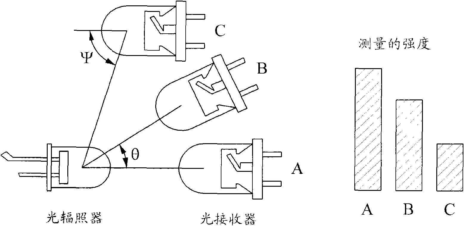
[0037] The infrared light may have a characteristic that the measured intensity varies depending on the distance between the light irradiator and the light receiver, the orientation of the light irradiator, and the orientation of the light receiver.

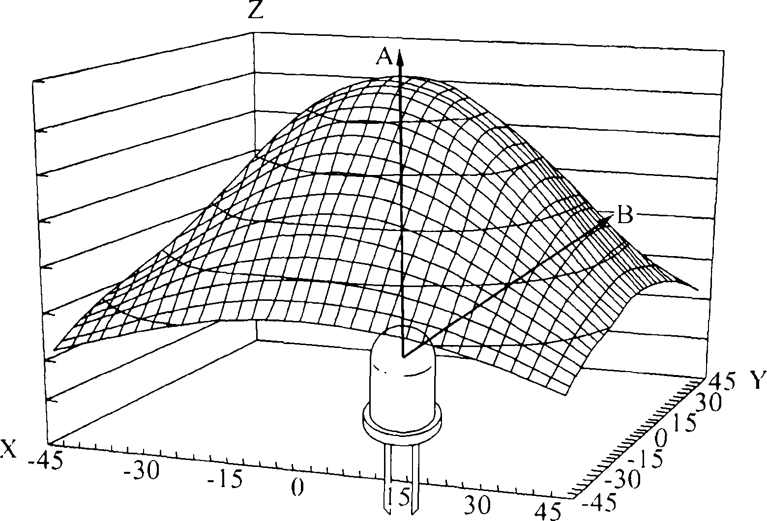
[0038] figure 1 Exemplary light emission directivity of infrared light is shown, showing that light reception intensity varies depending on the orientation of emitted infrared light.

[0039] refer to figure 1 , the infrared light may have a characteristic that the light-receiving intensity of the infrared light at a fixed distance from where the light receiver is located varies according to the direction of the light irradiator as the dire...


PUM


Abstract

A system and method for estimating position and orientation is provided. The system may measure the intensity of irradiated light irradiated by each light irradiator through each light receiver, and may estimate the position and location of the remote device based on the measured intensity, light receiving directivity, and light emitting directivity. direction.

Description

[0001] This application claims the benefit of Korean Patent Application No. 10-2010-0038338 filed with the Korean Intellectual Property Office on April 26, 2010, the disclosure of which is hereby incorporated by reference. technical field [0002] One or more embodiments in the following description relate to a system and method for estimating the position and orientation of an object, and more particularly, to a motion sensing method for estimating the position and orientation of an object using the attenuation characteristics of infrared light method. Background technique [0003] A method for estimating a three-dimensional (3D) position in space (hereinafter, 3D position) and the direction of a moving object or target has been mainly used in the fields of film, graphics, and animation to use relatively expensive and large-scale motion capture equipment in 3D spatial sensing of motion of objects, humans or animals. [0004] However, as motion sensing technology for consum...

Claims


Application Information

Patent Timeline
Patent Type & Authority Applications(China)
IPC IPC(8): G01S1/70G01S5/16G01S3/78
CPCG01S5/163A63F13/219G01B11/026G01B11/14
Inventor 方远喆李炯旭金相贤李基赫许成国韩在泫
Owner SAMSUNG ELECTRONICS CO LTD
Why Eureka
Try Eureka