
Computer equipment with automatic dust removal function

An automatic dust removal, computer technology, applied in the direction of pollution prevention methods, electrical digital data processing, cleaning methods and appliances, etc., can solve the problems affecting the circulation of hot and cold airflow of the casing, blocking the air inlet, etc.

Inactive Publication Date: 2011-12-14
HONG FU JIN PRECISION IND (SHENZHEN) CO LTD +1
View PDF2 Cites 8 Cited by
  • Summary
  • Abstract
  • Description
  • Claims
  • Application Information

AI Technical Summary

Problems solved by technology

However, when the outside air enters the air inlet, it will be mixed with dust and other impurities. These dusts are easy to accumulate at the air inlet. If this happens for a long time, it will block the air inlet and seriously affect the circulation of hot and cold air inside and outside the cabinet.

Method used


Image

  • Computer equipment with automatic dust removal function
  • Computer equipment with automatic dust removal function
  • Computer equipment with automatic dust removal function

Examples


Embodiment Construction

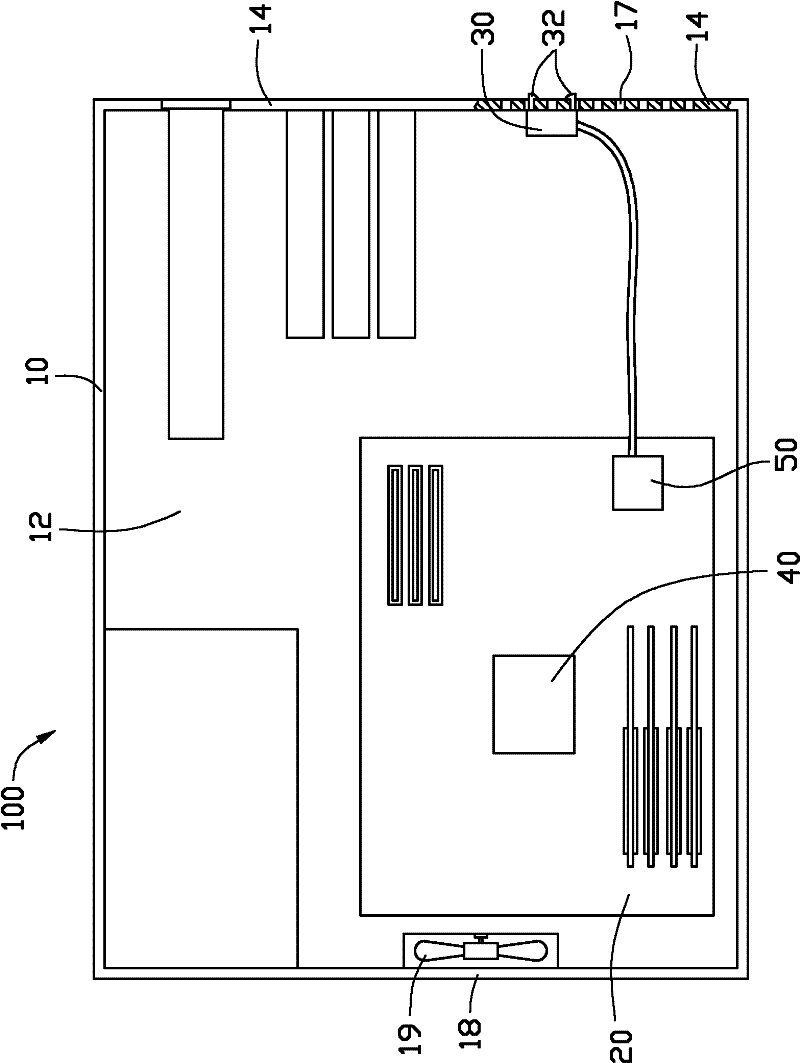
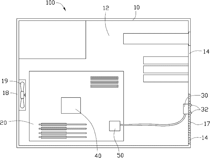
[0025] see figure 1 , the computer equipment 100 includes a casing 10, a circuit board 20 accommodated in the casing 10, and a vibrating element located on the inner wall of the casing 10. In this embodiment, the vibrating element is a vibrating motor 30 .

[0026] The casing 10 is in the shape of a hollow cuboid, and includes a rectangular first panel 12 and a side panel 14 vertically extending from a periphery of the first panel 12 . The casing 10 further includes a second panel opposite to the first panel 12 and covering the end of the side panel 14 . In order to clearly show the internal structure of the casing 10, the second panel is omitted in the figure.

[0027] An air inlet and an air outlet 18 are defined on the side panel 14 . The air outlet 18 passes through the side plate 14 , so that the internal system of the casing 10 communicates with the external environment. A fan 19 is disposed at the air outlet 18 for extracting the air in the casing 10 to the outside....


PUM


Abstract

A computer device with automatic dust removal function, comprising a casing and a central processing unit, the casing is provided with an air inlet, the casing is provided with a vibrating element at the air inlet, the central processing unit and the vibrating element A control device is arranged between, and the central processing unit sends a control signal to the control device, so that the control device controls the vibration of the vibrating element, and vibrates the casing through the vibrating element to shake off the dust accumulated at the air inlet. The computer equipment can realize the function of automatic dust removal.

Description

technical field [0001] The invention relates to an electronic device, in particular to a computer device with an automatic dust removal function. Background technique [0002] Computer equipment generally includes a casing and a circuit board housed in the casing, and a number of electronic components are arranged on the circuit board. Since the electronic components will generate a lot of waste heat during operation, in order to remove the waste heat from the electronic components in time to ensure the normal operation of the electronic components, the industry usually attaches a heat sink on the circuit board to dissipate the heat of the electronic components to the system At the same time, an air outlet is set on one side of the casing, and a fan is arranged at the air outlet to extract the hot air in the system to the outside. In order to strengthen the circulation of hot and cold air inside and outside the system, an air inlet is usually set up on the other side of the...

Claims


Application Information

Patent Timeline
IPC IPC(8): G06F1/16G06F1/18B08B17/00
Inventor 林宜滢郑浩德
Owner HONG FU JIN PRECISION IND (SHENZHEN) CO LTD
Features
  • Generate Ideas
  • Intellectual Property
  • Life Sciences
  • Materials
  • Tech Scout
  • Unparalleled Data Quality
  • Higher Quality Content
  • 60% Fewer Hallucinations
Learn More