
High density computer equipment storage systems

a computer equipment and high density technology, applied in the direction of electrical apparatus casings/cabinets/drawers, furniture parts, instruments, etc., can solve the problems of high cost, uneconomically feasible optimization performance, and broader competition between standard components, so as to achieve the effect of increasing the density of computer equipmen

Inactive Publication Date: 2005-02-01
HEWLETT-PACKARD ENTERPRISE DEV LP
View PDF62 Cites 84 Cited by
  • Summary
  • Abstract
  • Description
  • Claims
  • Application Information

AI Technical Summary

Benefits of technology

This invention is a system designed to maximize the density of computers that may be provided in a given space. Several features of the invention enable one to provide a higher density of computer systems at a site. Preferably, the computers are built from standardized or readily-available components, except for the chassis herein described.
One way in which the present invention conserves space and increases computer density is to eliminate the need for access to both the front and back of a computer. This is accomplished by an inventive chassis design in which ports for items requiring physical access are placed only at the front of the chassis. Items requiring physical access include, but are not limited to: various data drives or storage devices and physical input and output sockets. Preferably, the rear of a computer chassis made according to the invention is free of any such access ports. However, this “front access” feature of the present invention does not require that each and every physical attachment to a computer be located in front of the machine. Desirably, those which require physical access periodically or would significantly hinder forward removal of the machine from a rack in which it may be stacked are provided for at the front of the chassis. At least those features located on the main board which would normally be accessed from behind and accessible data drives are provided for in the front of the inventive chassis.
The above-described chassis configuration allows for effective placement of computer components in a back-to-back arrangement within a rack or other supporting structure. This back-to-back placement of computer components within a rack forms a highly desirable aspect of the invention. Such placement often doubles or further multiplies the density potential for rack computer systems, e.g., those in which the computers would otherwise be mounted one unit deep. The back-to-back mounting of computer chassis may also involve the back-to-back placement of full-function computers linked to one another or the back-to-back placement of a computer and a device such as a drive array serving the computer which it abuts.
The backspace and optional sidespace between the computers or rack sides may be used in another advantageous manner. Especially where maintaining a lower environmental temperature is a concern, a flow reversed from that described above will be advantageous. Such reversed flow may be accomplished by drawing ambient air by fans and / or a partial vacuum through the computer chassis past heat-generating components and venting it from the common space between the computers by a hood or plenum, vent or other means. Common ductwork may take the heated air out of the site. Alternately, it may be preferred that each hood independently exhausts air out of the site in which the computers are located. Providing front-to-back flow will cool computer components as well as help maintain lower ambient temperatures than possible with other high-density network computer solutions. As desired above, it is preferred that the flow of cooling gas is directed to or by hot-running or temperature sensitive components.

Problems solved by technology

Standardized components also face broader competition regarding performance.
In contrast, even when custom components are desired, it is often not economically feasible to optimize performance.
Although the number of smaller computers available for duty where space conservation is important has increased, they are typically very expensive.
Also, these smaller custom computer systems often suffer in the areas of computing speed and system reliability relative to computers using less costly standardized components.
It should be noted, however, that additional factors affect the performance of existing space-saving computer systems.
The compaction of layout in shrinking main board sizes results in component crowding and imparts additional design constraints which hinder design for optimal performance.
Crowding can adversely affect the manner in which components are connected as well as result in significant heat dissipation problems.
Further compromises are often made in shrinking computer sizes.
As with main boards designed for small size, these units often lag in performance relative to their standardized counterparts.
The use of custom components introduces further difficulties when they break down.
Supply issues can be such a difficulty as to make it more feasible to replace an entire machine so as not to lose its computing power for an extended time, rather than wait for repair components necessary to get the existing machine up and running.
This difficulty is often compounded by an increased failure rate experienced with custom components.
In contrast, when any portion of a server fails, the whole system may go down.
However, they have not gained wide acceptance.
Many of the racks are filled with cumbersome computers mounted on sliders which are attached through mounting holes provided in the front and back of the rack.
It is this latter design aspect which not only results in inefficiency in the amount of access space required, but also in the frequent inefficiencies associated with having to administer services to both sides of a computer.

Method used


Image

  • High density computer equipment storage systems
  • High density computer equipment storage systems
  • High density computer equipment storage systems

Examples


Embodiment Construction

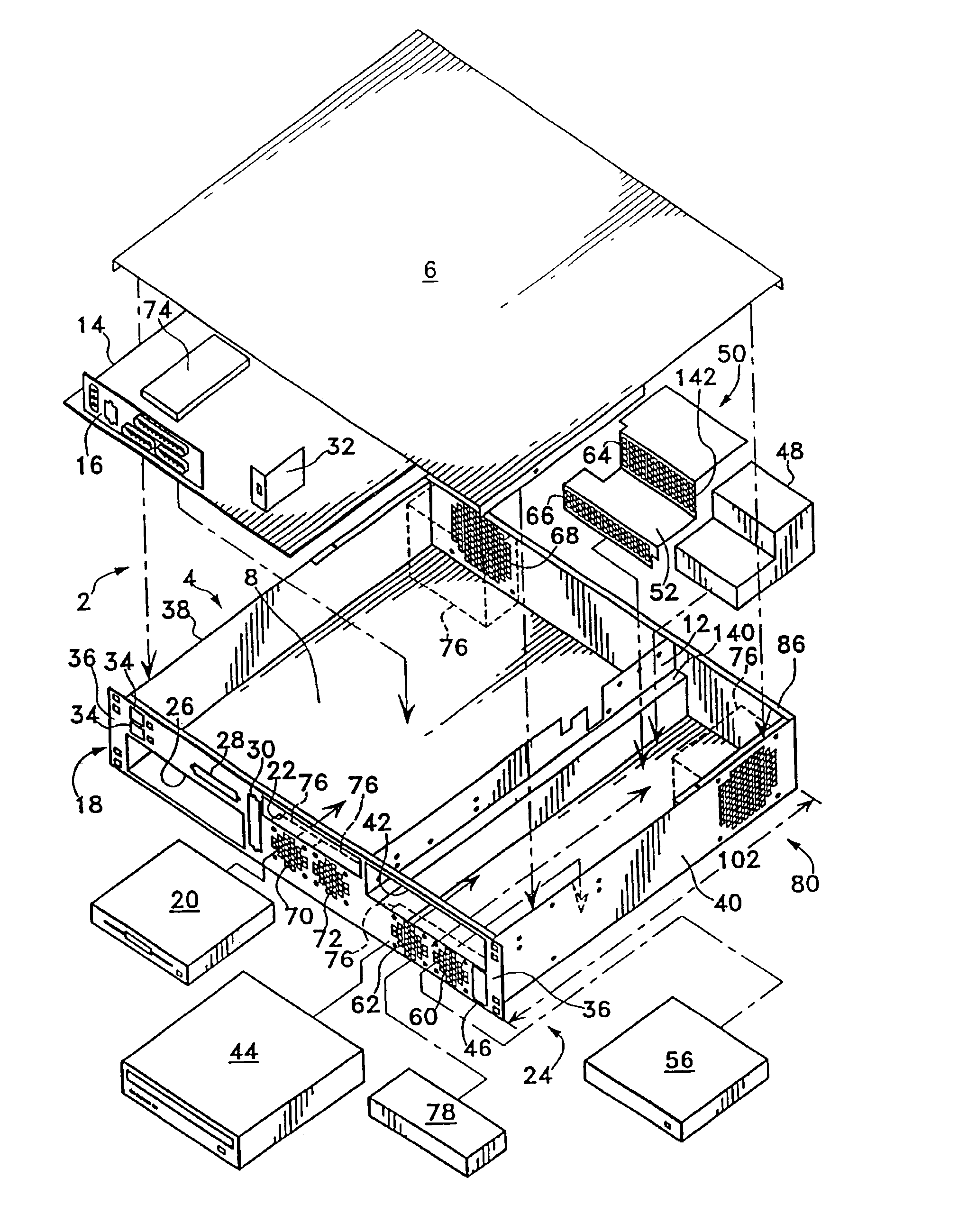
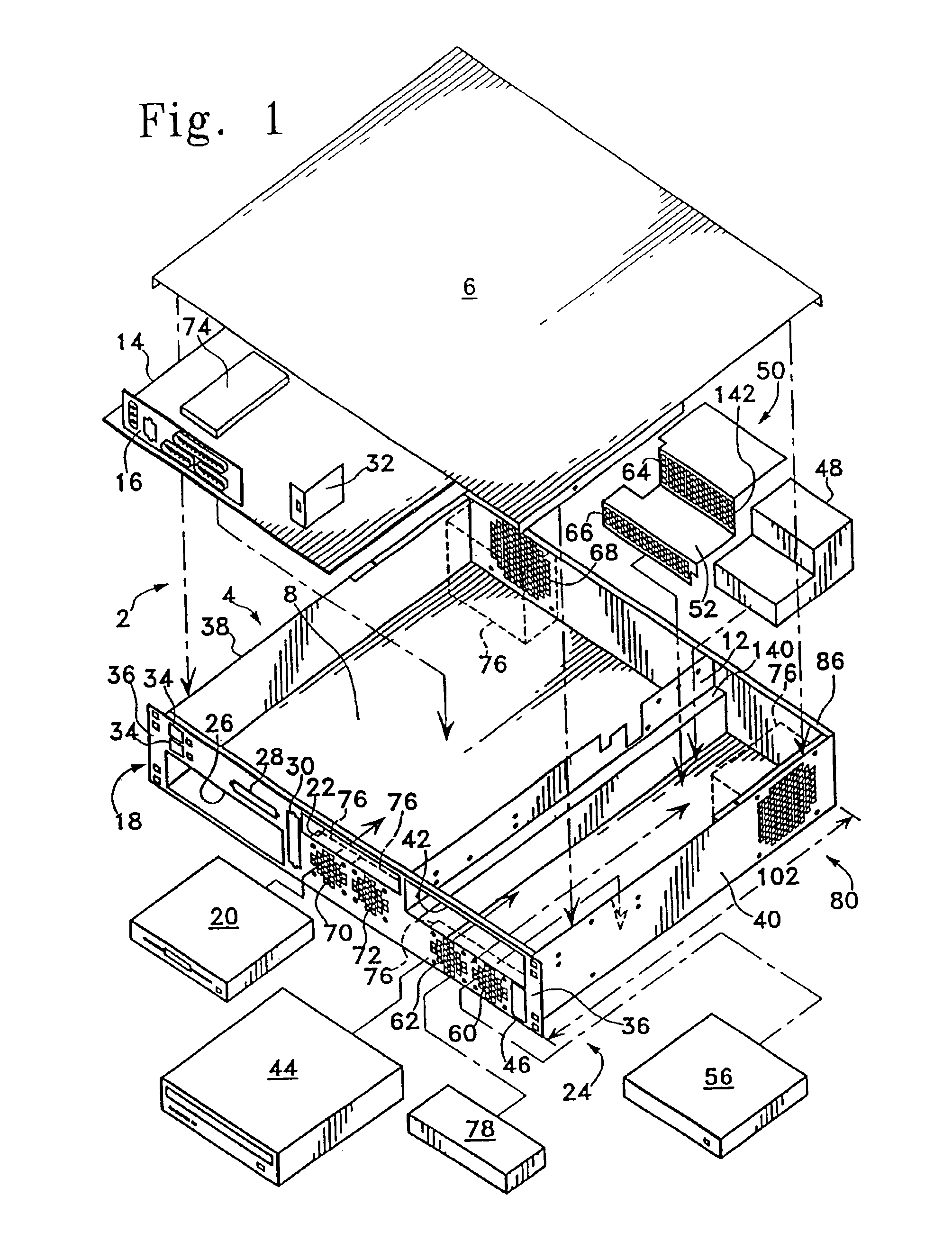
FIG. 1 shows a configuration of the inventive chassis as it may be assembled with standard components. Although the use of standard components is preferred, of course, none of the components must be so. The chassis 2 will usually include a chassis body 4 and a chassis cover 6. A main board compartment 8, and a power supply compartment 10 separated by a baffle 12 are optionally provided. Preferably, the main board compartment 8 is sized to fit an ATX form factor main board 14. Preferred main boards include models N44BX, L44GX, 810, 810E and C440GX by Intel, Inc. Such main boards typically include an I / O shield 16. The chassis 2, is preferably made of zinc plated mild steel sheet metal, with the front panel 18 painted. Rivets, welds or other suitable fastening methods may be used to secure various components and hold the chassis body 4 in shape.

The main board compartment 8 is preferably of a height sufficient to include room for a 3.5 inch disk drive 20 above main board 14 in a port 2...


PUM


Abstract

A computer is provided having a main board with I / O connectors mounted thereon, and a chassis including a front panel providing access to the I / O connectors and to all components requiring intermittent access provided for the computer.

Description

FIELD OF THE INVENTIONThis relates to the manner in which computers are configured and provided in a given area in order to conserve space and deal with cooling issues associated with housing a large number of computers. Aspects of the invention assist with increasing the density at which computers may be provided, particularly in a network server or host environment.BACKGROUND OF THE INVENTIONMany computers today are assembled from components built to one or more industry standards. The use of standardized components using specific interfaces allows for ease of supply, efficiency in production, and competitiveness in pricing. A further advantage associated with the use of standardized computer components, as opposed to custom pieces, is that of performance.The dollar-for-dollar performance advantage of many standardized components over similar custom components can be viewed as a beneficial consequence of the balance between the resources invested in each product and the efforts to...

Claims


Application Information

Patent Timeline
Patent Type & Authority Patents(United States)
IPC IPC(8): G06F1/20G06F1/18
CPCG06F1/18G06F1/20H05K7/20736H05K7/20727H05K7/1487
Inventor COGLITORE, GIOVANNIGALLO, NIKOLAIRANDALL, JACK
Owner HEWLETT-PACKARD ENTERPRISE DEV LP
Learn More