Techniques for Data Center Cooling

a technology for data centers and cooling systems, applied in cooling/ventilation/heating modifications electrical apparatus casings/cabinets/drawers, etc., can solve problems such as inefficiency, data center air cooling systems are not designed to handle thermal load, and increase power levels pose heat management challenges

Active Publication Date: 2008-11-20
GLOBALFOUNDRIES US INC
View PDF66 Cites 76 Cited by
  • Summary
  • Abstract
  • Description
  • Claims
  • Application Information

AI Technical Summary

Problems solved by technology

Increasing power levels pose challenges with regard to heat management.
Typically, the servers are air cooled and, in most cases., the data center air cooling systems are not designed to handle the thermal load.
Inefficiencies arise, however, when cooled air is supplied and returns directly to the air cooling unit without circulating through the equipment.
Inefficiencies can also arise when heated exhaust air, rather than returning to the air cooling unit, recirculates back into the equipment.
This problem is compounded in data centers where the hot isle / cold isle arrangement is not employed.
Recirculation difficulties can be most severe for equipment located at the tops of racks.

Method used


Image

  • Techniques for Data Center Cooling
  • Techniques for Data Center Cooling
  • Techniques for Data Center Cooling

Examples


Embodiment Construction

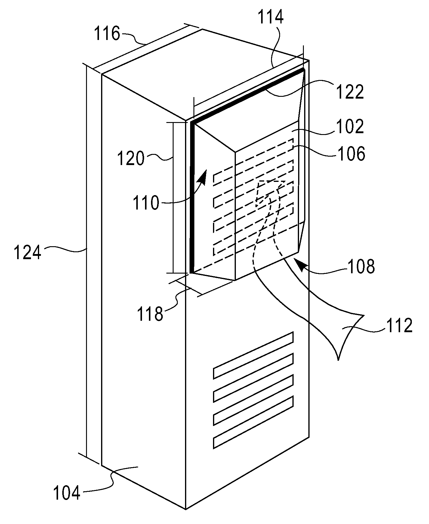
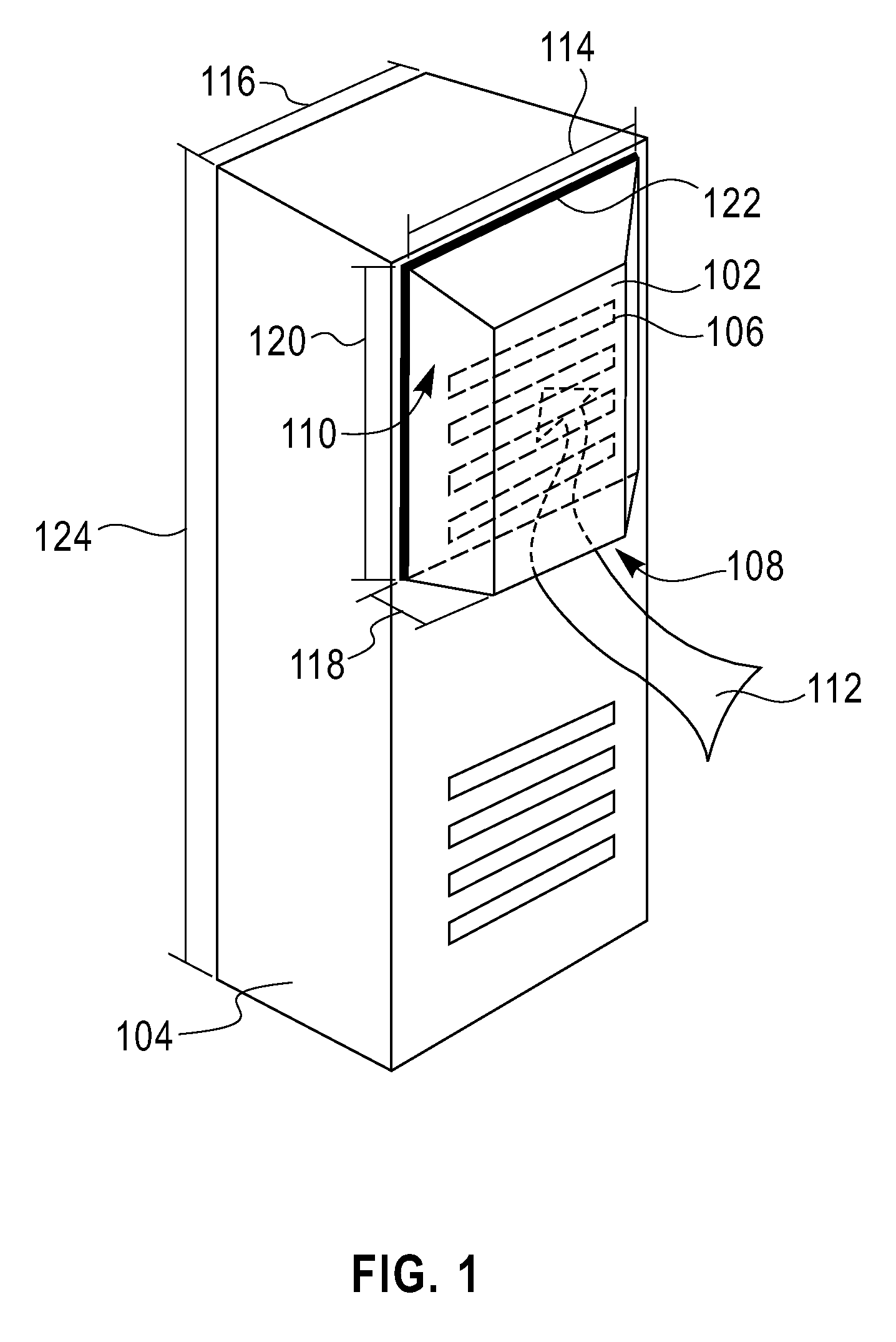
[0022]FIG. 1 is a diagram illustrating exemplary computer equipment rack 104 having air inlet redirection duct 102 mounted thereto. As will be described in detail below, an air inlet redirection duct can increase the efficiency of a data center cooling system by helping to minimize air recirculation effects and to prevent cooled air from being cycled without passing through the equipment.

[0023]Computer equipment rack 104 comprises air inlet ports, perforations, vents, holes or slots (hereinafter “air inlets”), e.g., air inlets 106, through which air is drawn to cool the computer equipment therein. Air inlets typically found on computer equipment racks are well known to those of ordinary skill in the art, and are not described further herein.

[0024]Air inlet redirection duct 102, when mounted to computer equipment rack 104 so as to surround at least a portion of air inlets 106, provides a continuous air passageway through open end 108 / open side 110 and into air inlets 106. e.g., as in...


PUM


Abstract

Techniques for cooling in a data center are provided. In one aspect a computer equipment rack is provided comprising one or more air inlets; one or more exhaust outlets, and one or more of: an air inlet duct mounted to the computer equipment rack surrounding at least a portion of the air inlets, the air inlet duct having a lateral dimension that approximates a lateral dimension of the computer equipment rack and a length that is less than a length of the computer equipment rack, and an air exhaust duct mounted to the computer equipment rack surrounding at least a portion of the exhaust outlets, the air exhaust duct having a lateral dimension that approximates the lateral dimension of the computer equipment rack and a length that is less than the length of the computer equipment rack.

Description

CROSS-REFERENCE TO RELATED APPLICATIONS [0001]This application is related to the commonly owned U.S. application Ser. No. ______, entitled “Techniques for Analyzing Data Center Energy Utilization Practices,” designated as Attorney Reference No. YOR920070242US1, filed herewith on the same day of May 17, 2007, the contents of which are incorporated herein by reference as fully set forth herein.FIELD OF THE INVENTION [0002]The present invention relates to cooling of computer equipment, and more particularly, to techniques for enhancing data center cooling systems.BACKGROUND OF THE INVENTION [0003]Computer equipment is continually evolving to operate at higher power levels. Increasing power levels pose challenges with regard to heat management. For example, many data centers now employ individual racks of blade servers that can develop 20,000 watts, or more, worth of thermal load. Typically, the servers are air cooled and, in most cases., the data center air cooling systems are not desi...

Claims


Application Information

Patent Timeline
Patent Type & Authority Applications(United States)
IPC IPC(8): H05K7/20
CPCH05K7/20736H05K7/20754H05K7/20745
Inventor CLAASSEN, ALANHAMANN, HENDRIK F.IYENGAR, MADHUSUDAN K.LACEY, JAMES ANDREWMARTIN, YVES C.SCHMIDT, ROGER R.VAN KESSEL, THEODORE GERARD
Owner GLOBALFOUNDRIES US INC
Why Eureka
Try Eureka