

Deployment method and device for logical nodes with successor backup relationship
A technology of logical nodes and backup relationships, which is applied in the field of communication, can solve problems such as backup failures, and achieve the effect of preventing backup failures and avalanche effects
- Summary
- Abstract
- Description
- Claims
- Application Information
AI Technical Summary
Problems solved by technology
Method used
Image

Examples
Embodiment 1
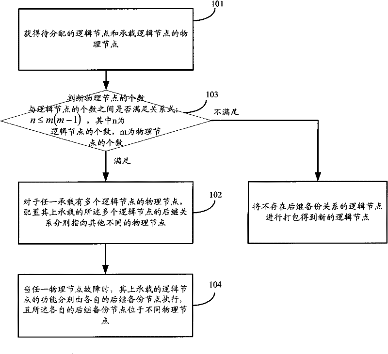
[0053] Embodiment 1 of the present invention provides a method for deploying logical nodes with a successor backup relationship, such as figure 1 shown, including:
[0054] Step 101, obtaining the logical node to be allocated and the physical node carrying the logical node;
[0055] Step 102, for any physical node carrying multiple logical nodes, configure the successor backup relationships of the multiple logical nodes carried on it to point to different physical nodes respectively.
[0056] After step 101, before step 102, also include:
[0057] Step 103, judging whether the relationship between the number of physical nodes and the number of logical nodes is satisfied: n≤m(m-1), wherein n is the number of logical nodes, and m is the number of physical nodes;
[0058] When the judgment result is satisfied, step 102 is executed.
[0059] The method also includes:
[0060] When the judgment result in step 103 is unsatisfactory, the logical nodes that do not have the success...
Embodiment 2
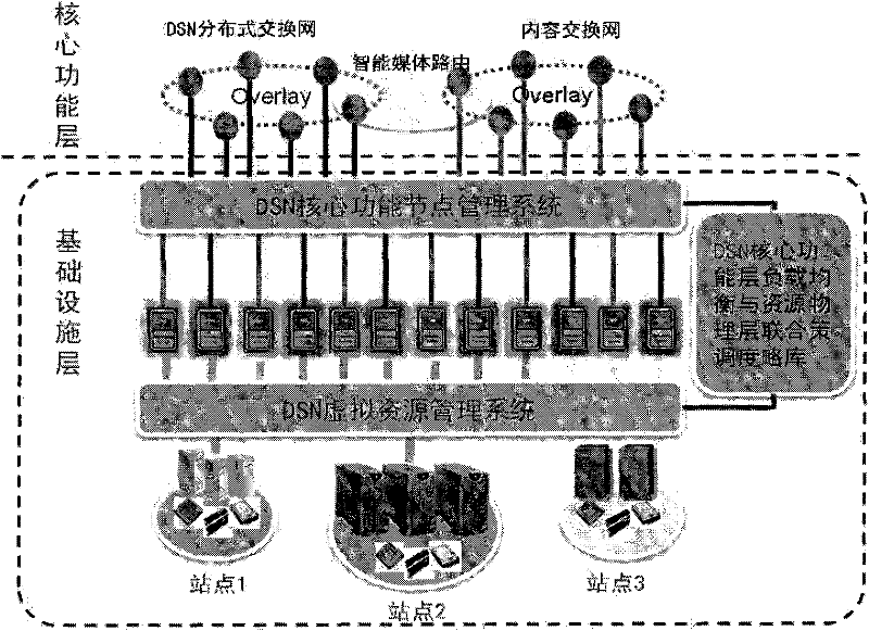
[0075] Embodiment 2 of the present invention provides a logical node deployment method, which is applied to figure 2 The system shown is described as an example, and the logical node is described by taking a virtual node as an example.
[0076] figure 2 The platform resource fusion architecture of China DSN is located at the infrastructure layer below the core function layer, including the DSN core function node management system, the DSN virtual resource management system and the joint strategy library:
[0077] Among them, the core function layer: includes several abstract telecommunication service capabilities (DSN distributed switching network, intelligent media routing and content switching network, etc.), and provides upward calling interfaces for various telecommunication application software. For example, voice services represented by VoIP, content sharing services represented by Streaming, etc. Each core function system uses distributed technology such as P2P to d...
Embodiment 3
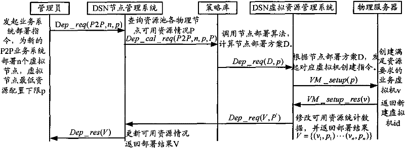
[0109] Embodiment 3 of the present invention provides a logical node deployment method. Considering that the resource capacity of each physical node in the actual system is limited, combined with the total amount and distribution of currently available physical resources in the actual system, the requirements of the integrated business system are given A method for deploying a logical node. The logical node is still described using the virtual node in Embodiment 2 as an example.
[0110] The virtual node deployment method in the third embodiment includes a node deployment algorithm alg_lb(n, m, P, p) that integrates load balancing requirements.
[0111] The starting point of the alg_lb algorithm is to achieve the goal of improving system reliability. Based on the principle of physical resource scheduling that averages the load pressure of physical nodes as much as possible, in step 3 of alg_core, according to the successor relationship (x, y) of the current deployment node and ...
PUM
 Abstract
Description
Claims
Application Information