Urban rail transit continuous basin beam

A kind of urban rail transit and basin-type technology, which is applied in bridges, buildings, etc., can solve the problems of unreasonable force of U-shaped beam structure, inability to apply in cross-crossing sections, and inability to cross large nodes, etc., to achieve high torsional strength , Reasonable structural stress, reducing visual effects

Active Publication Date: 2011-12-21
BEIJING URBAN CONSTR DESIGN & DEV GRP CO
View PDF6 Cites 14 Cited by
  • Summary
  • Abstract
  • Description
  • Claims
  • Application Information

AI Technical Summary

Problems solved by technology

[0003] The purpose of the present invention is to provide a continuous pot beam for urban rail transit, which solves the problems that the existing U-shaped beam structure is unreasonable in force, unable to span large nodes, and cannot be applied in crossover sections; The bridge and the U-beam landscape in the section of the crossing line or at a larger node are not well coordinated.

Method used


Image

  • Urban rail transit continuous basin beam
  • Urban rail transit continuous basin beam
  • Urban rail transit continuous basin beam

Examples


Embodiment 1

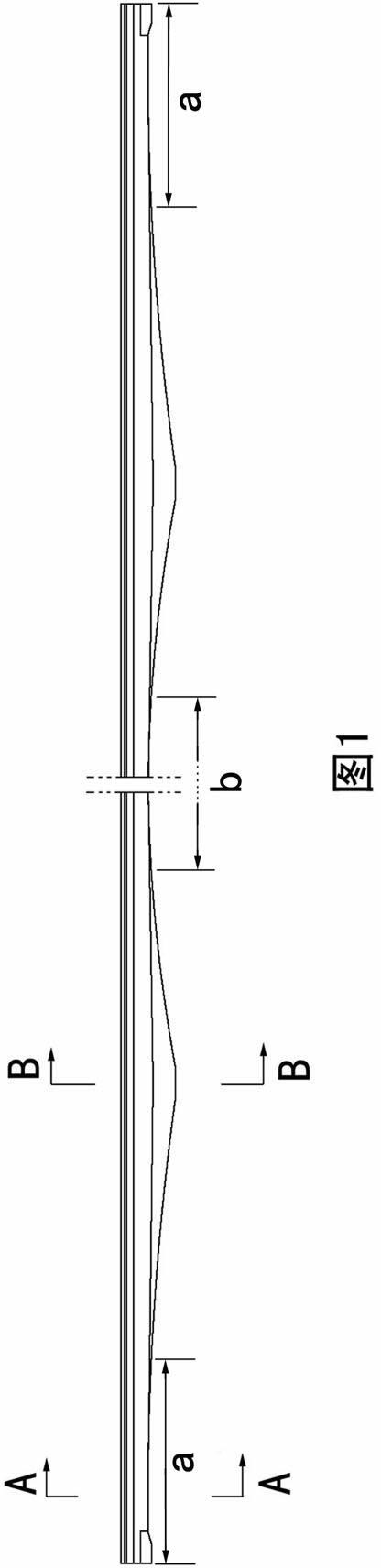
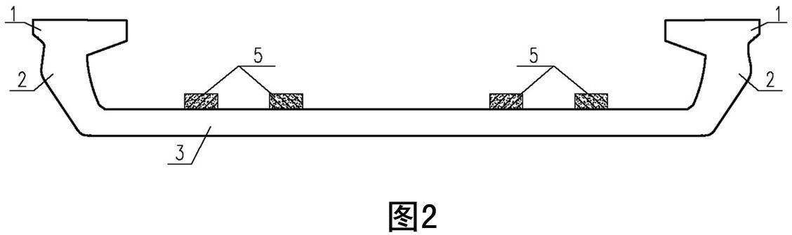
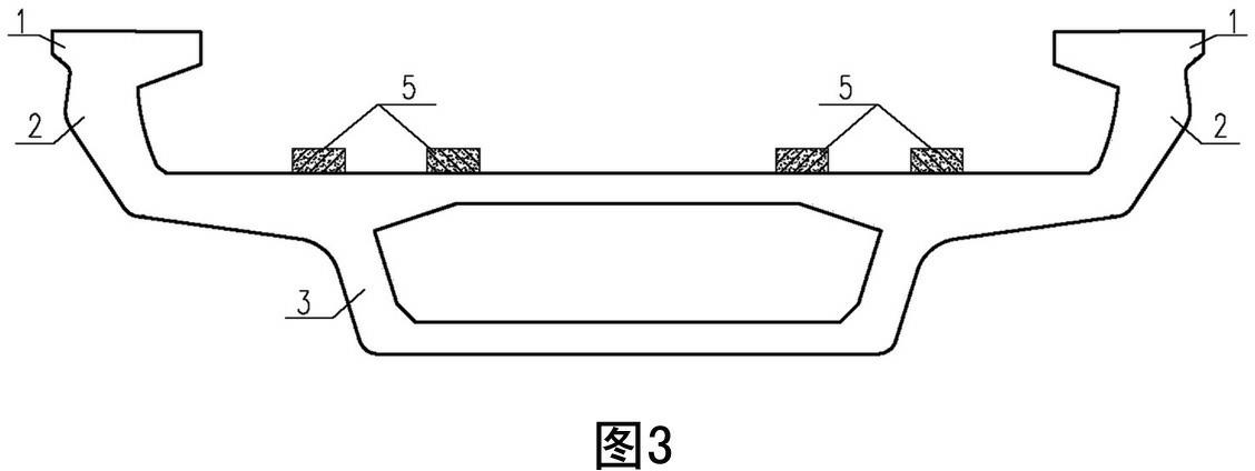
[0028] Embodiment one sees Figure 1-3 As shown, this urban rail transit continuous pot beam is set in the crossover section or where it needs to cross a larger node, and is connected with the existing U-shaped beam. The beam body is supported by the support base plate 3, the The upper web 2 on both sides of the bottom plate and the flange plate 1 on the top of the upper web are connected to form a channel with a pot-shaped cross section. At least two pairs of rail bearing platforms 5 are arranged on the supporting bottom plate, which are fixedly connected along the length direction of the beam body. There is a power supply device, a power supply cable support body 6 and a communication signal cable groove 7. The span of the beam body is 40 meters to 80 meters. Layer, the rest of the beam body support bottom plate 3 is a closed box shape, and the lower surface of the single-layer support bottom plate of the side fulcrum section and the mid-span straight section is a smooth tra...

Embodiment 2

[0031] Embodiment two see Image 6 , Figure 7 , the power supply device on the beam body is a catenary power supply device, including a catenary column 9, which is a prestressed reinforced concrete column or a steel column, and the catenary column 9 is fixedly connected to the flange plate 1 of the beam body . The catenary column 9 is fixedly connected to the beam body with a flange plate connected by pre-embedded anchor bolts. The catenary column 9 can be either a non-compensated catenary column or a compensated catenary column.

Embodiment 3

[0032] Embodiment three see Figure 8 , Figure 9 , and the second embodiment differs in that the catenary column 9 is fixedly connected to the support floor of the beam between the two pairs of rail platforms 5 .


PUM


Abstract

The invention relates to an urban railway traffic continuous basin type beam. A beam body of the continuous basin type beam is a passage which has the basin-shaped cross section and is formed by connecting a support bottom plate, upper web plates and wing edge plates, the upper web plates are arranged at both sides of the support bottom plate, the wing edge plates are arranged at the tops of the upper web plates, at least two pairs of rail carrying tables are arranged on the support bottom plate, a power supply device, power supply cable support bodies and communication signal cable grooves are fixedly connected in the length direction of the beam body, the span of the beam body is 40m to 80m, the support bottom plate of the beam body at the side fulcrum region section and the middle spanflat and straight section is in a single layer, the rest support bottom plate of the beam body is in a closed opening box shape, in addition, the lower surface of the single-layer support bottom plate of the side fulcrum region section and the middle span flat and straight section is in smooth transition connection with the bottom surface of the box shape. The beam is arranged at the crossed transition line region section or a place required to span a large node, the urban railway traffic continuous basin type beam belongs to a bridge structural form integrating the thin-wall opening U-shapedbeam and the closed opening box-shaped beam into a whole, the problems that the ordinary railway traffic U-shaped beam cannot span large node and cannot be applied to the crossed wire transition region section are solved, and the application range of the U-shaped beam is enlarged.

Description

technical field [0001] The invention relates to a viaduct track bed supporting member for supporting rails. Background technique [0002] Known U-shaped beams, such as the Chinese patent application whose publication number is CN101120140A and titled "U-shaped beam for urban rail transit", are single-line U-shaped beams for rail transit, and are only suitable for bridges with a medium span of about 30 meters in urban rail transit. When crossing the crossover section or when it is necessary to cross a large node, the existing U-shaped beam structure is not reasonable enough to meet the requirements, so it is necessary to use other beam types, and the use of other beam types will affect the landscape. This restricts the application of U-shaped beams. Contents of the invention [0003] The purpose of the present invention is to provide a continuous pot beam for urban rail transit, which solves the problems that the existing U-shaped beam structure is unreasonable in force, ...

Claims


Application Information

Patent Timeline
Patent Type & Authority Applications(China)
IPC IPC(8): E01D2/00
Inventor 阙孜张宏杰潘彪白唐瀛朱君卿张晓林张娜李文会
Owner BEIJING URBAN CONSTR DESIGN & DEV GRP CO
Why Eureka
Try Eureka