Shear Type Stiffened Metal Damper

A metal damper, shear type technology, applied in the direction of building components, shockproof, etc., can solve problems such as initial buckling stiffness, achieve the effect of easy welding quality, convenient welding, energy dissipation capacity and stability

Inactive Publication Date: 2011-12-21
SHANGHAI SAFE SEISMIC RETROFIT & VIBRATION CONTROL TECH
View PDF4 Cites 17 Cited by
  • Summary
  • Abstract
  • Description
  • Claims
  • Application Information

AI Technical Summary

Problems solved by technology

[0005] The purpose of the present invention is to provide a shear type stiffening metal damper with stiffening ribs installed outside the shear plate in the plane, so as to overcome the existing buckling when the steel plate is sheared in the plane and the initial rigidity of the steel plate when the force is outside the plane. low disadvantage

Method used


Image

  • Shear Type Stiffened Metal Damper
  • Shear Type Stiffened Metal Damper
  • Shear Type Stiffened Metal Damper

Examples


Embodiment 1

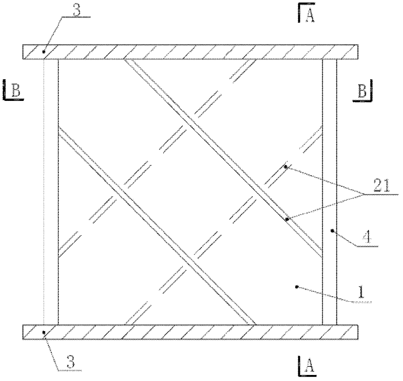
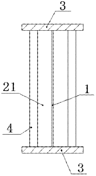
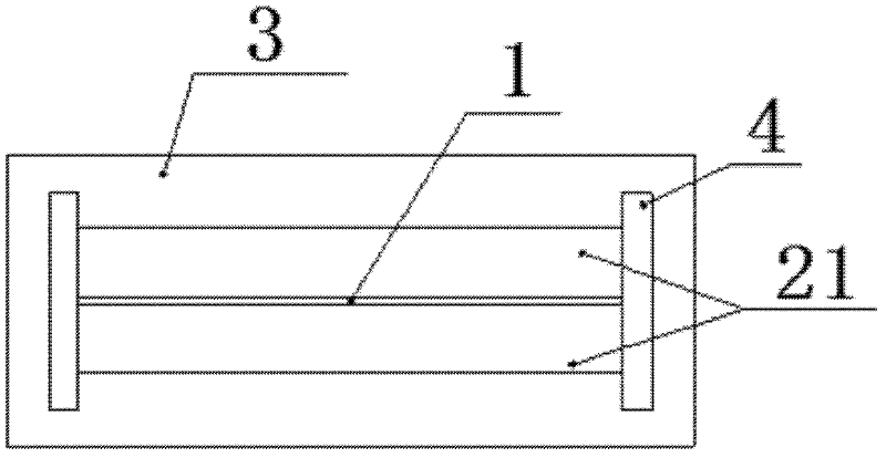
[0043] Such as figure 1 , figure 2 and image 3 as shown, figure 2 for figure 1 A schematic cross-sectional view along the A-A direction in , image 3 for figure 1 A schematic cross-sectional view along the B-B direction. The figure includes an energy-dissipating steel plate 1, the left and right sides of the energy-dissipating steel plate 1 are provided with stiffeners 21 respectively, the upper and lower ends of the energy-dissipating steel plate 1 are respectively provided with horizontal connecting steel plates 3, and the front end of the energy-dissipating steel plate 1 is And the rear end is equipped with flange plate 4 respectively.

[0044] The stiffener 21 on the left side of the energy dissipation steel plate 1 and the stiffener 21 on the right side of the energy dissipation steel plate 1 are arranged obliquely and anti-symmetrically on both sides of the energy dissipation steel plate 1 . There are two stiffeners 21 on the left side of the energy dissipation...

Embodiment 2

[0046] Such as Figure 4 , Figure 5 and Figure 6 as shown, Figure 5 for Figure 4 A schematic cross-sectional view along the A-A direction in , Figure 6 for Figure 4 A schematic cross-sectional view along the B-B direction. The figure includes an energy-dissipating steel plate 1, the left and right sides of the energy-dissipating steel plate 1 are provided with stiffeners 22 respectively, the upper and lower ends of the energy-dissipating steel plate 1 are respectively provided with horizontal connecting steel plates 3, and the front end of the energy-dissipating steel plate 1 is And the rear end is equipped with flange plate 4 respectively.

[0047] The stiffener 22 on the left side of the energy dissipation steel plate 1 and the stiffener 22 on the right side of the energy dissipation steel plate 1 are arranged on both sides of the energy dissipation steel plate 1 in the horizontal direction and the vertical direction respectively. Two stiffeners 22 are arranged ...

Embodiment 3

[0049] Such as Figure 7 , Figure 8 and Figure 9 as shown, Figure 8 for Figure 7 A schematic cross-sectional view along the A-A direction in , Figure 9 for Figure 7 A schematic cross-sectional view along the B-B direction. The figure includes an energy-dissipating steel plate 1, the left and right sides of the energy-dissipating steel plate 1 are provided with stiffeners 23 respectively, the upper and lower ends of the energy-dissipating steel plate 1 are respectively provided with horizontal connecting steel plates 3, and the front end of the energy-dissipating steel plate 1 is And the rear end is equipped with flange plate 4 respectively.

[0050]The stiffeners 23 on the left side of the energy dissipation steel plate 1 and the stiffeners 23 on the right side are obliquely anti-symmetrically arranged on both sides of the energy dissipation steel plate 1 . A stiffening rib 23 is provided on the left side of the energy-dissipating steel plate 1 , and a stiffening ...


PUM


Abstract

The invention discloses a shear-type stiffened metal damper, which comprises an energy-dissipating steel plate, stiffening ribs are respectively arranged on the left and right sides of the energy-dissipating steel plate, horizontal connecting steel plates are respectively arranged on the upper end and the lower end of the energy-dissipating steel plate, Flange plates are arranged at the front end and rear end respectively, the stiffeners on the left side and the right side of the energy dissipation steel plate are arranged symmetrically or asymmetrically, and the stiffeners on the same side of the energy dissipation steel plate are arranged without crossing. The invention utilizes the advantages of relatively large initial rigidity when the steel plate is stressed in the plane, and prevents the buckling of the energy-dissipating steel plate by means of stiffening, thereby ensuring the energy-dissipating capacity and stability of the damper; There are no cross welds, and the stiffeners can be set in full length without truncating, which is convenient for welding, and the welding quality is easy to guarantee.

Description

technical field [0001] The invention relates to the anti-seismic field of building engineering structures, in particular to a shear type stiffening metal damper. Background technique [0002] The energy dissipation and shock absorption of building structures refers to the installation of appropriate energy dissipation components in the building structure. The energy dissipation components can be composed of energy dissipation and shock absorption devices and supporting components such as braces, walls, beams or nodes. The metal energy dissipator is an energy-dissipating shock-absorbing device with superior energy-dissipating performance, simple structure, convenient manufacture, low cost and easy replacement. It can be used as an energy-dissipating unit or limiting device in conjunction with a seismic-isolation support or a seismic-isolation system, and it can also be used alone in a building structure as an energy-dissipating device to provide additional damping and stiffne...

Claims


Application Information

Patent Timeline
Patent Type & Authority Applications(China)
IPC IPC(8): E04B1/98
Inventor 陈明中黄坤耀李静王鸿博徐继东陈维清
Owner SHANGHAI SAFE SEISMIC RETROFIT & VIBRATION CONTROL TECH
Why Eureka
Try Eureka