
A floating positioning cone connection device

A connecting device and floating positioning technology, applied in vibration suppression adjustment, non-rotation vibration suppression, bolts, etc., can solve the problems of difficult processing, poor positioning and connection accuracy, and achieve simple and compact structure, low manufacturing cost, and wide application range. wide effect

Inactive Publication Date: 2011-12-21
NO 722 RES INST OF CHINA SHIPBUILDING IND
View PDF6 Cites 3 Cited by
  • Summary
  • Abstract
  • Description
  • Claims
  • Application Information

AI Technical Summary

Problems solved by technology

However, there are inevitably some problems in both types of positioning connection methods. For example, the shortcoming of the straight positioning pin positioning connection device is to use the gap to compensate the distance between two pairs of pins and holes (or multiple positioning pins, holes) and the positioning holes of the connected parts. The errors caused in the manufacturing process lead to poor positioning connection accuracy and collision, impact, noise and other problems in the connection structure due to gaps; the disadvantage of the conical pin positioning connection device is to ensure that two pairs of pins, holes (or multiple positioning pins, holes) positioning connection accuracy, because the deviation value of manufacturing accuracy decreases with the increase of the number of positioning pins and holes, the smaller the deviation value of the hole spacing, the more difficult it is to process

Method used


Image

  • A floating positioning cone connection device
  • A floating positioning cone connection device
  • A floating positioning cone connection device

Examples


Embodiment Construction

[0014] The present invention will be further described below in conjunction with accompanying drawings and examples of use.

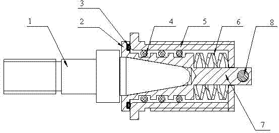
[0015] Such as figure 1 , 2 As shown, the present invention provides a floating positioning conical connection device, which includes a conical pin 1, a floating conical sleeve 2 and a floating body seat 5, the floating body seat 5 is sleeved with a floating conical sleeve 2 for positioning connection with the conical pin 1, The floating cone sleeve 2 and the floating body seat 5 float in a radial gap of 360°, and the radial gap between the floating cone sleeve 2 and the floating body seat 5 is provided with a floating damping ring 4, and the gap can be adjusted by selecting different diameters of the floating damping ring 4 adjust. The flexible damping of the floating damping ring 4 can overcome two (or a plurality of positioning holes) positioning taper pins and positioning hole machining assembly spacing deviation.

[0016] The tail of the above-m...


PUM


Abstract

The invention relates to the technical field of universal positioning connection, and provides a floating positioning cone connecting device. The device comprises a cone pin, a floating cone sleeve and a floating body seat, wherein the floating cone sleeve which is used to be connected with the cone pin in a positioning way is sleeved in the floating body seat; the floating cone sleeve and the floating body seat are moved at the interval of 360 DEG in the radial direction; and a floating damping ring is arranged at the radial clearance between the floating cone sleeve and the floating body seat. The device can self-adapt to error values in the deviation permissible range of the space between a positioning cone pin and a positioning hole, can achieve the effects of vibration isolation and buffering and has the advantages of simple and compact structure, low manufacturing cost, convenience of use and maintenance and the like.

Description

technical field [0001] The invention relates to the technical field of universal positioning connection, in particular to a floating positioning conical connection device. Background technique [0002] In the application of positioning connection devices, according to the structure type, it can be divided into two types of positioning connection devices: straight positioning pins (positioning straight holes) and conical positioning pins (positioning conical holes). However, there are inevitably some problems in both types of positioning connection methods. For example, the shortcoming of the straight positioning pin positioning connection device is to use the gap to compensate the distance between two pairs of pins and holes (or multiple positioning pins, holes) and the positioning holes of the connected parts. The errors caused in the manufacturing process lead to poor positioning connection accuracy and collision, impact, noise and other problems in the connection structur...

Claims


Application Information

Patent Timeline
Patent Type & Authority Applications(China)
IPC IPC(8): F16B19/02F16F15/073F16F15/04
Inventor 鲍秀森朱癸宇
Owner NO 722 RES INST OF CHINA SHIPBUILDING IND
Learn More