
A method and device for realizing database trigger function

A trigger and database technology, applied in the field of communication, to improve efficiency, meet application requirements, and save time

Inactive Publication Date: 2011-12-21
ZTE CORP
View PDF2 Cites 3 Cited by
  • Summary
  • Abstract
  • Description
  • Claims
  • Application Information

AI Technical Summary

Problems solved by technology

[0007] The technical problem to be solved by the present invention is to provide a method and device for realizing the database trigger function, so as to solve the problem in the prior art that the application module cannot be notified of database data changes in units of tables

Method used


Image

  • A method and device for realizing database trigger function
  • A method and device for realizing database trigger function
  • A method and device for realizing database trigger function

Examples


Embodiment Construction

[0035] In order to solve the problem in the prior art that the application module database data change cannot be notified in units of tables, the present invention provides a method and device for realizing the database trigger function. The present invention will be further described in detail below in conjunction with the accompanying drawings and embodiments . It should be understood that the specific embodiments described here are only used to explain the present invention, not to limit the present invention.

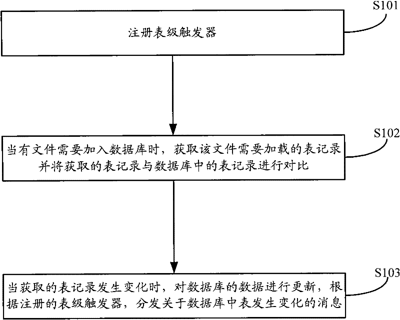
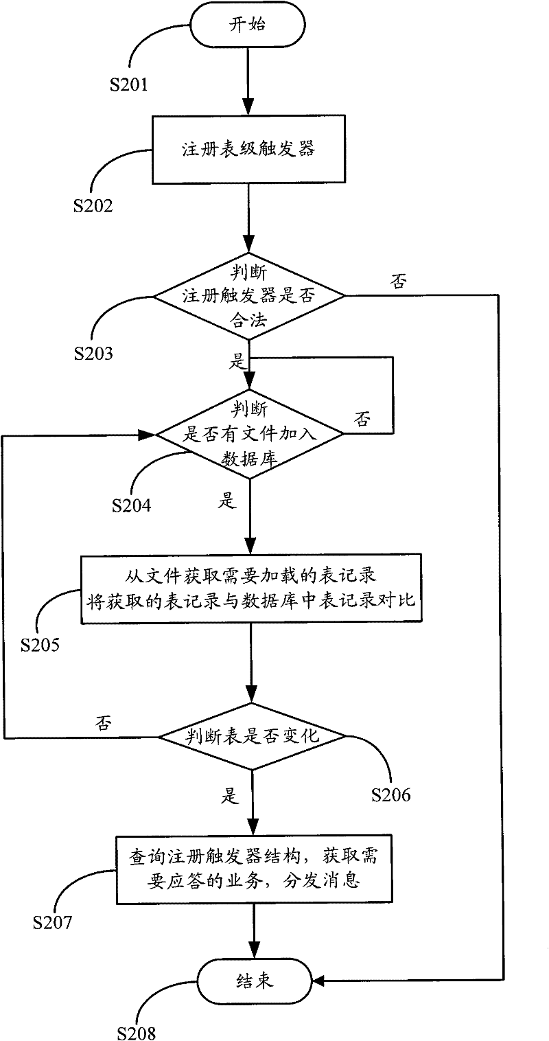
[0036] like figure 2 As shown, the embodiment of the present invention relates to a method for realizing the database trigger function, comprising the following steps:

[0037] Step S101, a registry-level trigger.

[0038] The application registers a table-level trigger. The registration trigger includes the specific application ID that needs to be notified when the subsequent message is triggered, and the table ID that needs to be triggered. The structure membe...


PUM


Abstract

A method and a device for realizing the function of database trigger are disclosed. The method includes the following steps: registering a table-level trigger (S101); obtaining a table record, which is needed to be loaded, from a file, when the file is needed to be added to the database, and comparing the obtained table record with a table record in the database (S102); updating the database when there is variation in the obtained table record, and distributing a message about variety of the table in the database according to the registered table-level trigger (S103). A function of triggering in table unit and informing an application module of the data in the database being varied is realized. The method enriches the function of database trigger, satisfies the application requirement of table-level triggering, saves the processing time of the trigger by the database, and enhances the efficiency of the data real-time synchronization at the foreground.

Description

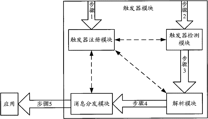
technical field [0001] The invention relates to the technical field of communication, in particular to a method and device for realizing the trigger function of a database. Background technique [0002] A trigger in a database is a stored procedure that improves the execution efficiency of an embedded system. In the embedded database, when the data changes, whether it is adding, deleting, or modifying the data, it is necessary to notify the application that the data it cares about has changed and the specific content of the change. The function of the trigger is to improve the real-time performance of the system and enhance the synchronization function of the system to external data. [0003] The specific implementation of embedded database triggers, as well as the collaborative relationship between modules, and the data processing flow, such as figure 1 shown. Among them, the trigger registration module is used to register triggers, providing a trigger registration struc...

Claims


Application Information

Patent Timeline
IPC IPC(8): G06F17/30
CPCG06F17/30289G06F16/21
Inventor 谭瑾博
Owner ZTE CORP
Learn More