an hdmi cable connector

A cable connector and connector technology, which is applied in the direction of connection, parts of connection devices, contact parts, etc., can solve the problems of high terminal arrangement density, complicated assembly process, and increased production costs, so as to improve production efficiency and Effects of quality rate, optimized component structure, and product size reduction

Inactive Publication Date: 2011-12-21
SHENZHEN TRONIXIN ELECTRONICS
View PDF4 Cites 11 Cited by
  • Summary
  • Abstract
  • Description
  • Claims
  • Application Information

AI Technical Summary

Problems solved by technology

[0002] A general HDMI cable connector includes a shell, a shielding shell, an insulating body, and a number of metal terminals mounted on the insulating body. However, the HDMI connector in the prior art uses the insulating body as the main component. The collocation and combination will bring many unfavorable factors to the process, such as:
[0003] 1. The metal terminal is inserted from the rear of the insulating body and is fixed by interfering with the terminal groove of the insulating body through the protrusions provided on the metal terminal fixing part. However, the HDMI connector with a single row of contact terminals has a large terminal arrangement density, and the terminal The required material and processing precision are high. When inserting into the terminal slot of the insulating body, special jigs must be used, which increases the production cost
[0004] 2. The shell is covered on the tongue plate extending forward from the main body of the insulating body, and is fixed by the buckle mechanism provided on the shell and the buckle mechanism provided on the main body of the insulating body. However, the tongue plate extending from the insulating body is relatively small. Long, its plug interface and terminal slot are built-in, first, the cost of mold opening is high; second, the assembly process is complicated, it is difficult to effectively control the product yield, and the productivity is low;

Method used


Image

  • an hdmi cable connector
  • an hdmi cable connector
  • an hdmi cable connector

Examples


Embodiment Construction

[0026] The following describes the present invention in further detail with reference to the accompanying drawings, taking a cable connector as an example.

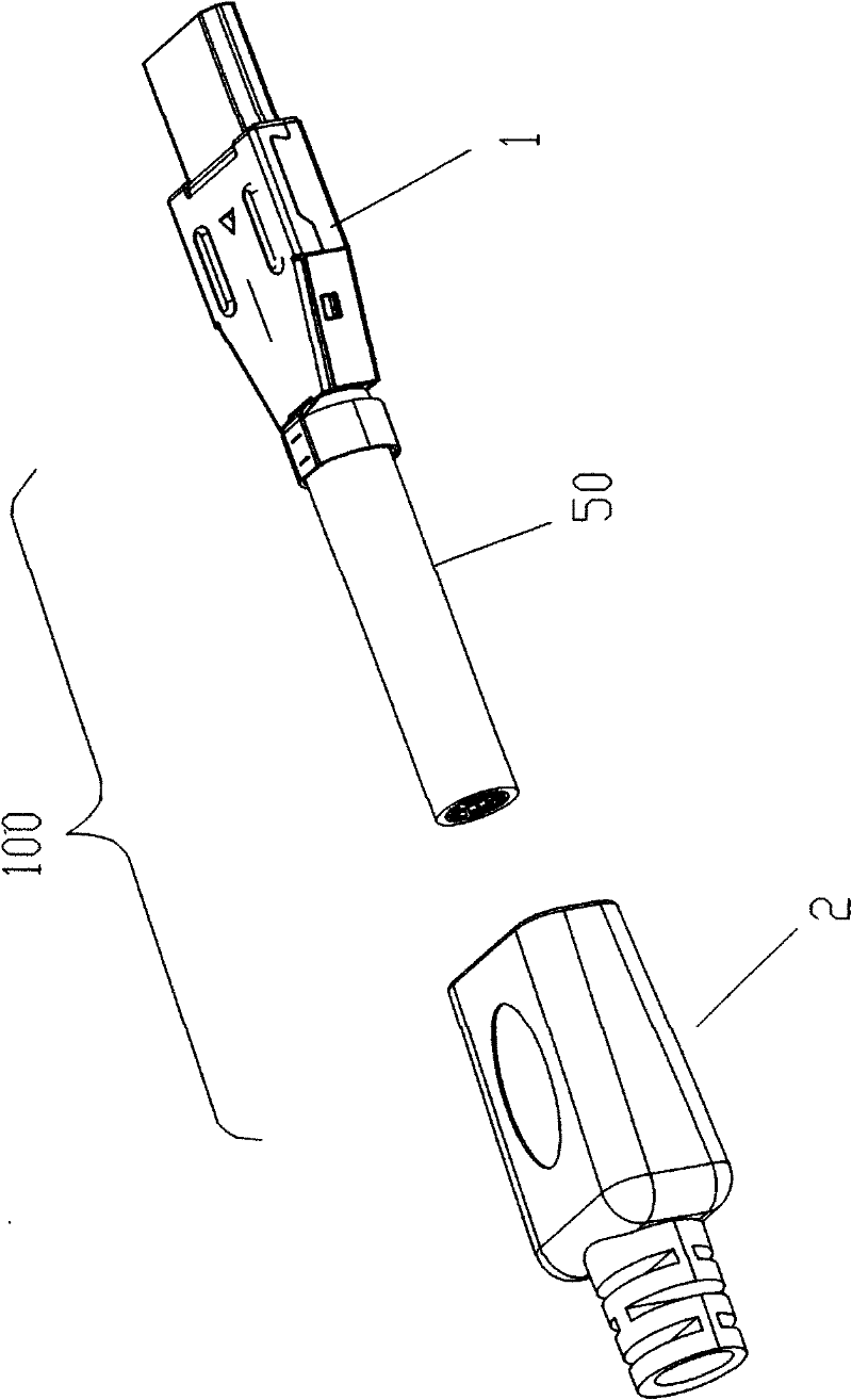
[0027] See figure 1 As shown, a cable connector (100) includes a connector body (1) and a shell (2) covering the back of the connector body (1). The shell (2) is injection molded. The main body (1) of the connector is encapsulated by a metal back shell (70), thereby avoiding adverse effects on the internal electrical connection performance of the main body (1) of the connector during injection molding of the shell (2).

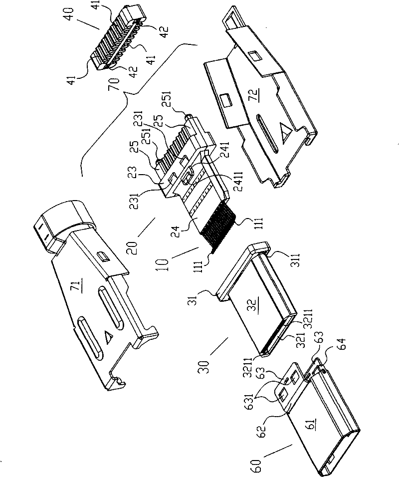
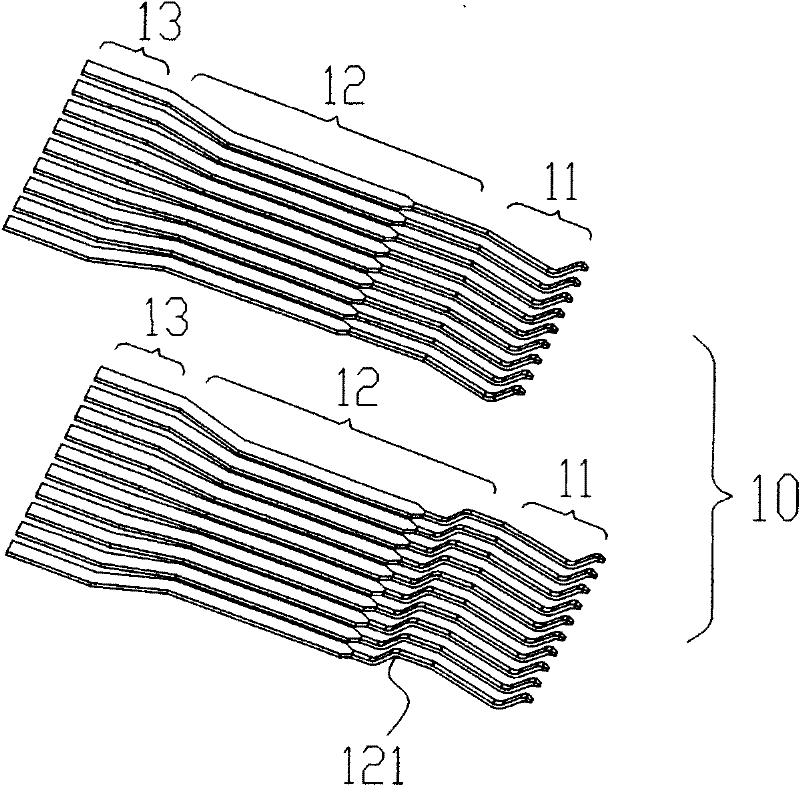
[0028] See figure 2 And refer to figure 1 , image 3 As shown, the connector body (1) includes a terminal group (10) and an insulating body (20) formed by inserting mold technology, and an insulating housing (30) that houses the front contact portion (11) of the terminal group (10), and connects The cable (50) from the terminal welding section (13) to the branch base (40), the metal front shell (60) covering ...


PUM


Abstract

An HDMI cable connector, comprising a connector main body and a shell covering the rear of the main body, the connector main body includes a terminal group and an insulating body, an insulating housing for accommodating the contact portion of the front section of the terminal group, and connecting the terminal welding section Cables to the distribution base, sleeve the insulating shell to the metal front shell of the insulating body, and the metal rear shell that encapsulates the welding section of the terminal to the wire distribution base, wherein the terminal group and the insulating body are integrated into the mold for injection molding A component, the single terminal in the one-piece component includes a contact section and a fixing section connecting the welding section, the insulating body in the one-piece component includes a first insulator and a second insulator; the insulating housing includes a basic part and its extended In the docking part, the back of the basic part runs through to the docking port in front of the docking part, and an inner cavity is provided. The inner cavity is provided with a terminal slot and penetrates with the notch on the front docking port. Through the above concept, a HDMI Design and construction of cable connectors.

Description

Technical field [0001] The invention relates to an electrical connector, in particular to an HDMI cable connector. Background technique [0002] A general HDMI cable connector includes a housing, a shielding shell, an insulating body, and a number of metal terminals mounted on the insulating body. However, the HDMI connector in the prior art uses the insulating body as the main component. Matching and combining brings many disadvantages to the process, such as: [0003] 1. The metal terminal is inserted from the back of the insulating body and fixed by interference with the terminal groove of the insulating body by the protruding thorns provided in the metal terminal fixing part. However, the HDMI connector with a single row of contact terminals has a high terminal arrangement density and the terminal The required material and high processing accuracy require special jigs to be used when inserting into the terminal slot of the insulating body, which increases the production cost. ...

Claims


Application Information

Patent Timeline
IPC IPC(8): H01R13/405H01R13/02H01R13/514
Inventor 邹凤根伊宏刚
Owner SHENZHEN TRONIXIN ELECTRONICS
Why Eureka
Try Eureka