Collector ring

A technology of collector rings and copper rings, applied in the field of collector rings, can solve the problems of finding no way out of the wire, increasing the difficulty of actual assembly operations, etc., and achieving the effect of preventing fires

Active Publication Date: 2014-06-11
洛阳聚科特种工程机械有限公司
View PDF6 Cites 0 Cited by
  • Summary
  • Abstract
  • Description
  • Claims
  • Application Information

AI Technical Summary

Problems solved by technology

[0003] Due to the limitation of the outlet position when assembling the existing collector rings and other equipment, there is no way to go out when assembling with equipment without a center outlet position, or when the wire outlet is from the center, it increases the difficulty of the actual operation of the assembly

Method used


Image

  • Collector ring
  • Collector ring
  • Collector ring

Examples


Embodiment Construction

[0024] The invention is further described below in conjunction with preferred embodiments:

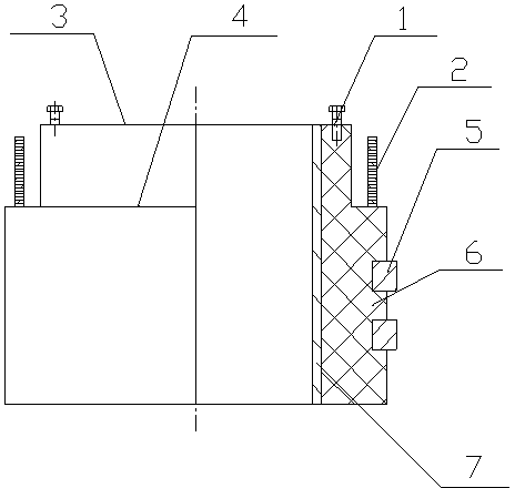
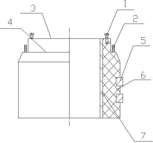
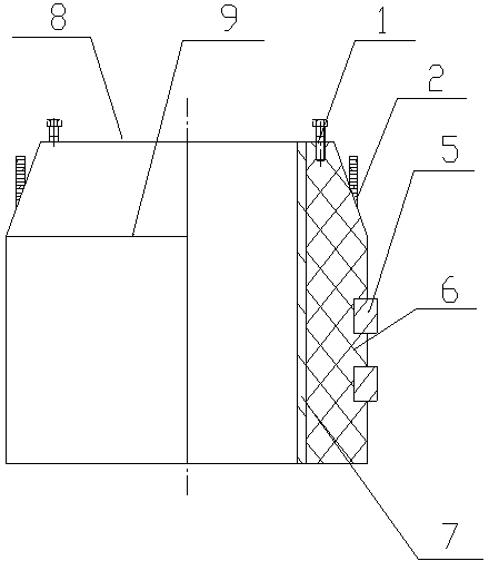
[0025] combine figure 1 , a collector ring, which is set as a structure in which a copper ring 5 and a resin 6 are poured into one body, and one end of the collector ring is provided with a step, and the step is divided into an upper end surface 3 and a lower end surface 4; the copper ring and the copper busbar 2 are formed from The interior of the pouring body is fixed, and an insulating layer is set between the copper busbar and the unconnected copper ring, and the outlet end of the copper busbar is located at 4 places on the lower end surface of the step of the collector ring. Bolts 1 are provided on the upper end surface of the stepped end of the collector ring to facilitate connection with other equipment; according to actual needs, the bolts can be evenly distributed on the upper end surface or set according to the situation. The collector ring is provided with a steel plate lin...


PUM


Abstract

The invention discloses a collector ring, which relates to a low voltage electrical appliance and aims to eliminate the restrictions of an outlet position in the assembly of the conventional collector ring and other equipment. The collector ring specifically has a structure formed by pouring copper rings (5) and resin (6) into a whole. One end of the collector ring is provided with a step. The copper ring (5) and a copper bus (2) are fixedly connected in a poured body. An insulating layer is arranged between the copper bus (2) and the copper ring (5) which is not connected with the copper bus (2). An outlet terminal of the copper bus (2) is positioned at the lower end face (4) of the step of the collector ring. Bolts (1) are arranged at the upper end face (3) of the step of the collector ring. The outside outlet of the collector ring can provide a rational outlet position for rotating equipment without a central outlet position so as to eliminate the restrictions of the outlet position in the assembly of the collector ring and the other equipment.

Description

technical field [0001] The invention relates to a low-voltage electrical appliance, in particular to a collector ring. Background technique [0002] There are two types of existing collector ring structures: one is a collector ring composed of copper rings and epoxy resin rings; the other is assembled with half copper rings, an insulating layer is added in the middle, and a bottom frame is assembled at the bottom. Collector rings; the outlet parts of these two collector rings are at the ends, and when combined with other equipment, the wires need to be outlet at the center. [0003] Due to the limitation of the outlet position during the assembly of existing slip rings and other equipment, no outlet method can be found in the assembly of equipment without a central outlet position, or when the outlet is from the center, the actual operation difficulty of the assembly is increased. Contents of the invention [0004] The technical problem to be solved by the invention is to...

Claims


Application Information

Patent Timeline
Patent Type & Authority Patents(China)
IPC IPC(8): H01R39/00H01R39/10H01R39/34
Inventor 代义军曹忠
Owner 洛阳聚科特种工程机械有限公司
Why Eureka
Try Eureka