Vacuum switch tube

A vacuum switch tube and shell technology, applied in electrical switches, high-voltage/high-current switches, high-voltage air circuit breakers, etc., can solve problems such as limiting the withstand voltage strength, and achieve the effect of high withstand voltage strength

Inactive Publication Date: 2011-12-21
SIEMENS AG
View PDF4 Cites 14 Cited by
  • Summary
  • Abstract
  • Description
  • Claims
  • Application Information

AI Technical Summary

Problems solved by technology

Therefore, it may easily cause discharge or flashover on the outer surface of the vacuum interrupter between the field control element and other

Method used


Image

  • Vacuum switch tube
  • Vacuum switch tube
  • Vacuum switch tube

Examples


Embodiment Construction

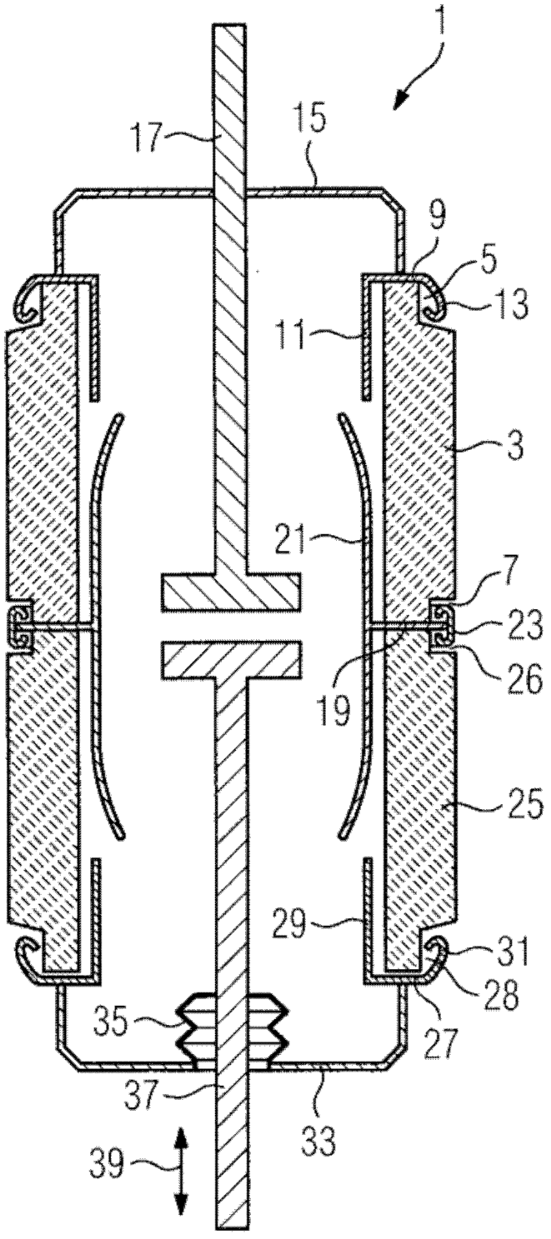
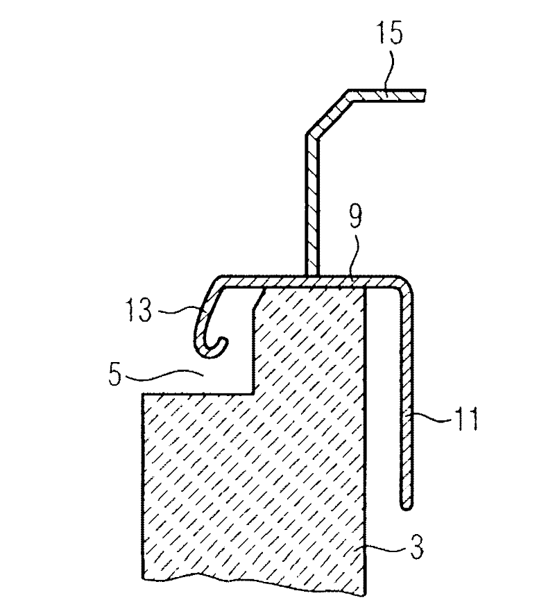
[0020] figure 1 A cross-sectional view of the vacuum interrupter 1 is shown. Such a vacuum interrupter 1 has an essentially cylindrical, electrically insulating first housing part 3 made of ceramic. The first housing part 3 has a substantially hollow-cylindrical shape and has a first recess 5 at one end face and a second recess 7 at the other end face. One end face of the first housing part 3 is vacuum-tightly connected to the first metal part 9 , eg vacuum-tightly welded. The first metal part 9 has a flange-shaped metal ring with a vapor barrier 11 inside the vacuum interrupter and a first field control element 13 at its radially outward end. The first metal part 9 is vacuum-tightly connected to the first metal cover 15 . The static contact 17 passes through the first metal cover 15 and is firmly inserted therein, for example by welding.

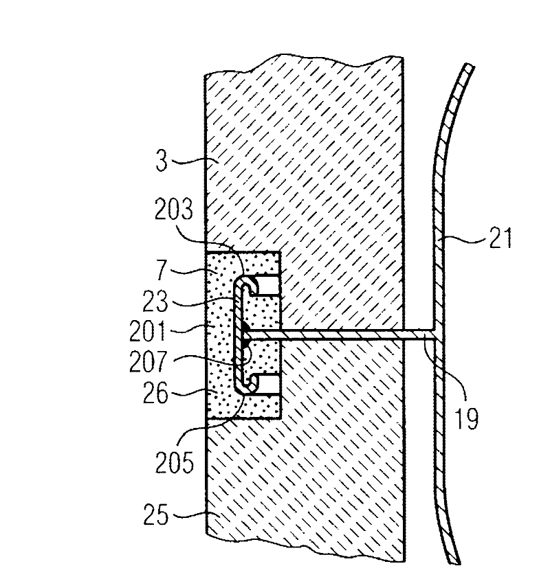
[0021] The other end face of the first housing part 3 is connected to the second metal part 19 in a vacuum-tight manner. The second m...


PUM


Abstract

The invention relates to a vacuum interrupter (1) with at least one substantially cylindrical, electrically insulating housing part (3), which is connected in vacuum-tight fashion to a metal part (9). In this case, the metal part has been provided with a field control element (13). The field control element (13) is arranged in a cutout (5) in the housing part (3) in such a way that the field control element (13) is arranged so as to be recessed with respect to the outer lateral surface of the housing part (3) or terminates flush with the outer lateral surface.

Description

technical field [0001] The invention relates to a vacuum interrupter having at least one substantially cylindrical, electrically insulating housing part which is connected vacuum-tight to a metal part, wherein the metal part is associated with a field control element . Background technique [0002] German utility model document DE 297 17 489 Ul already discloses a vacuum interrupter of this type. In such a vacuum interrupter, the field control element is arranged on the outer surface of the electrically insulating housing part and protrudes radially beyond the outer surface. Therefore, it may easily cause discharge or flashover on the outer surface of the vacuum interrupter between the field control element and other conductive parts of the vacuum interrupter (such as other field control elements), thereby limiting the so-called External compressive strength. Contents of the invention [0003] The technical problem to be solved by the present invention is to provide a v...

Claims


Application Information

Patent Timeline
IPC IPC(8): H01H33/66
CPCH01H2033/66276H01H2033/66284H01H33/66261H01H2033/66292
Inventor U.舒曼
Owner SIEMENS AG
Why Eureka
Try Eureka