Method for determining degradation and/or efficiency of laser modules and laser units

A laser and laser power technology, applied in lasers, laser devices, laser parts and other directions, can solve problems such as time-consuming, high cost, failure, etc.

Active Publication Date: 2011-12-21
TRUMPF LASER GMBH CO KG
View PDF1 Cites 4 Cited by
  • Summary
  • Abstract
  • Description
  • Claims
  • Application Information

AI Technical Summary

Problems solved by technology

The disadvantage of series connection is that when one module fails, the other modules also fail at the same time
Plus, it would be time consuming and costly

Method used


Image

  • Method for determining degradation and/or efficiency of laser modules and laser units
  • Method for determining degradation and/or efficiency of laser modules and laser units
  • Method for determining degradation and/or efficiency of laser modules and laser units

Examples


Embodiment Construction

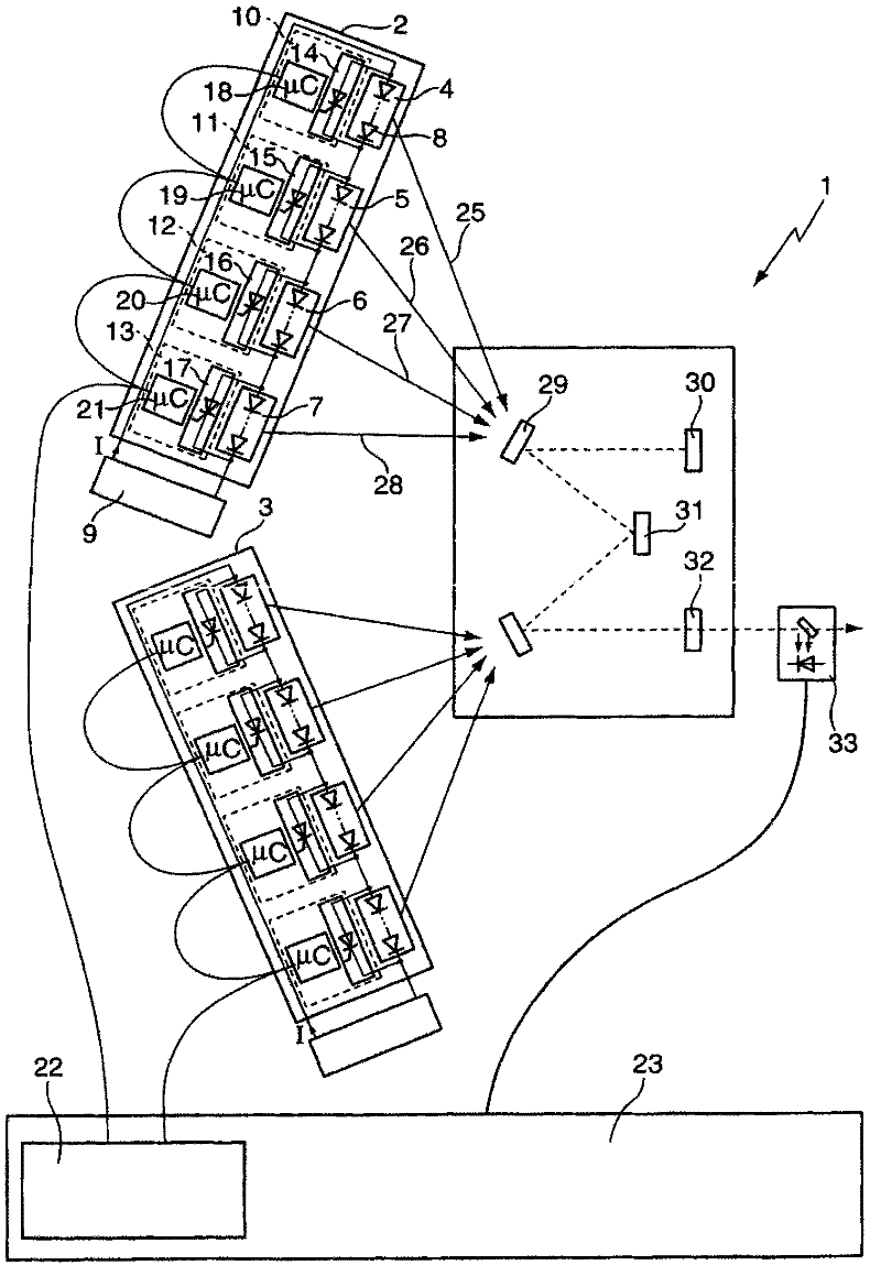
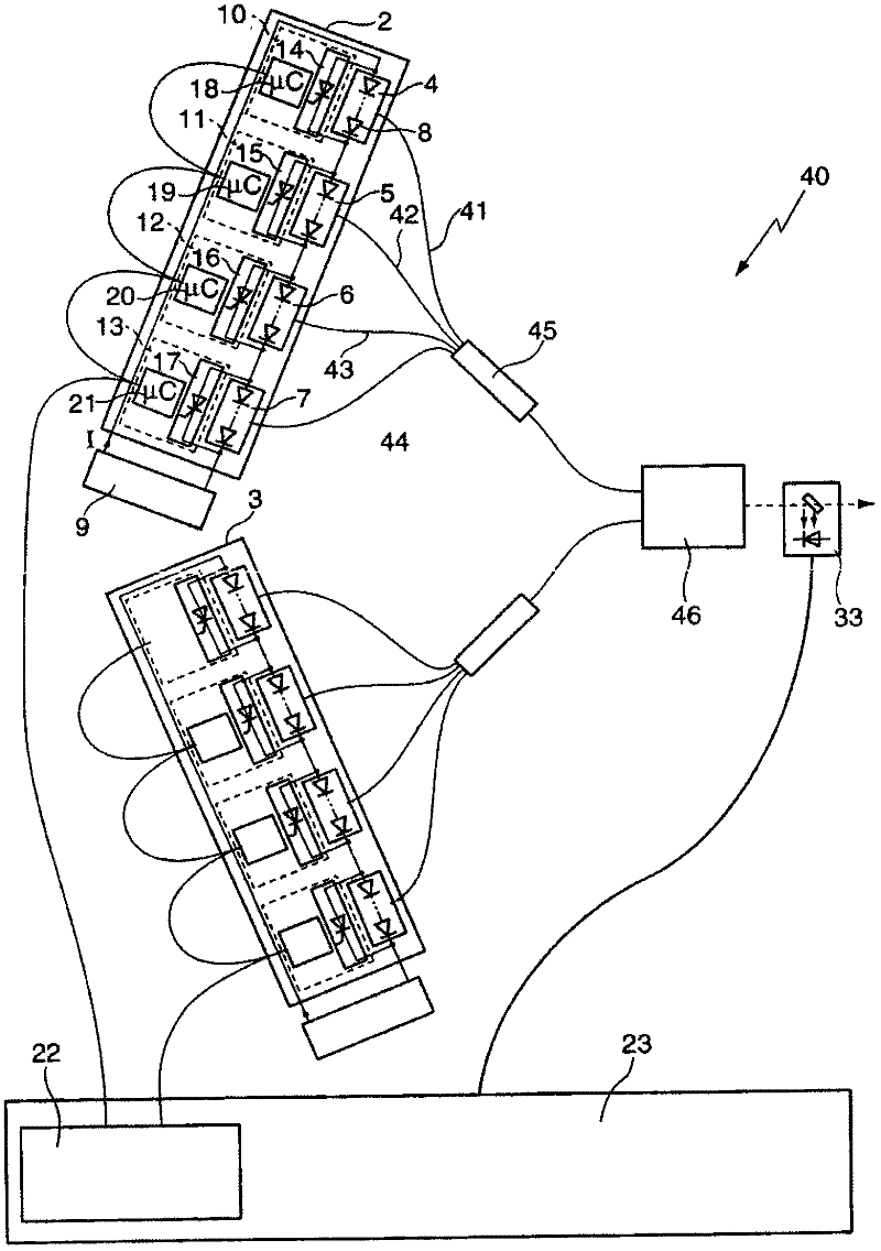
[0033] figure 1 A laser 1 is shown, wherein the laser 1 is designed as a disc laser and comprises two laser units 2 , 3 . The laser units 2 , 3 are constructed in the same manner, so that only the laser unit 2 will be described below.

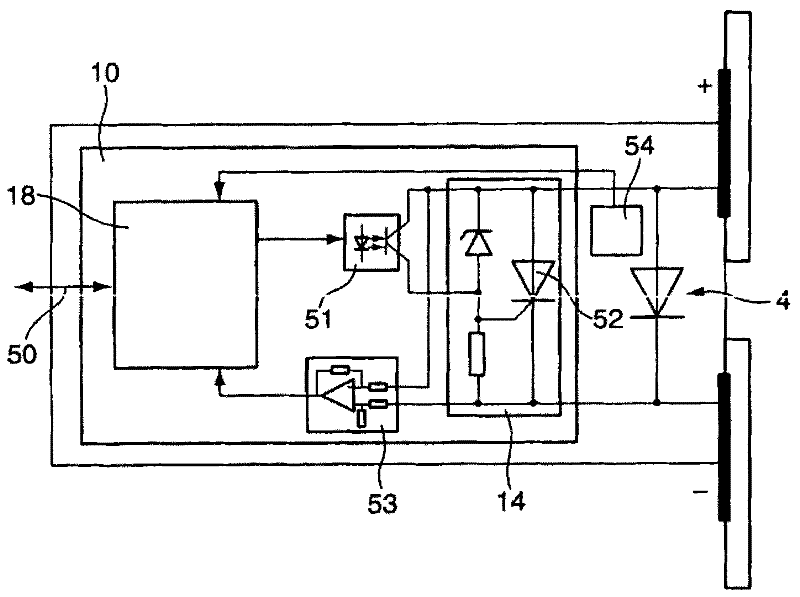
[0034] In this exemplary embodiment, the laser unit 2 has four laser modules 4 to 7 which are connected in series, each laser module 4 to 7 having one or more laser diodes 8 connected in series. The individual laser modules 4 to 7 are connected to a common power supply 9 so that the same current flows through all laser modules 4 to 7 . The voltage drop across the individual laser modules 4 to 7 can be different. A bypass structure 10 to 13 is associated with each laser module 4 to 7 , by means of which the relevant laser module 4 to 7 can be bypassed when the switching elements 14 to 17 are electrically conductively connected. Each bypass structure 10 to 13 has a microcontroller 18 to 21 . The microcontrollers 18 to 21 of the laser unit 2 a...


PUM


Abstract

A method for determining the degradation and/or efficiency of a laser unit (2, 3) having a plurality of laser modules (4-7) connected in series, wherein a bypass system (10-13) by which the associated laser module (4-7) can be bypassed is connected in parallel to each laser module (4-7), comprises the following steps: a. determining a first laser power for a first number of laser modules (4-7); b. activating the bypass system (10-13) of at least one laser module (4-7) of the first number of laser modules (4-7) such that at least one laser module (4-7) is bypassed; c. determining a second laser power for a second number of laser modules (4-7), wherein the second number equals the first number without the bypassed laser modules (4-7); d. determining the difference between the first and second laser power.

Description

technical field [0001] The invention relates to a method for determining the degradation and / or efficiency of a laser module of a laser module structure comprising a plurality of laser modules, each of which is connected in series, each laser being connected in parallel with a bypass structure, the associated laser Modules can be bypassed by means of the bypass structure. Furthermore, the invention relates to a laser unit having a power supply to which a plurality of laser modules connected in series with one another are connected, each laser module comprising at least one laser diode and a controllable bypass structure associated with each laser module. Background technique [0002] To achieve high power output levels, laser modules must supply high currents. Therefore, it is advantageous to connect the laser module in series to the power supply. The current is therefore the same for all laser modules. Voltages are cumulative. The disadvantage of series connection is th...

Claims


Application Information

Patent Timeline
Patent Type & Authority Applications(China)
IPC IPC(8): H01S5/40G01R31/26H01S3/0941
CPCG01R31/2635H01S5/0021H01S5/4018H01S5/4012H01S3/0625H01S3/0941H01S3/0604
Inventor T・K・诺特海斯R・弗莱格M・利尔曼A・基利
Owner TRUMPF LASER GMBH CO KG
Why Eureka
Try Eureka