skull lock

A skull and locking piece technology, applied in the field of medical skull lock, can solve the problems of falling off of the locking piece, long operation time, affecting the operation effect, etc., and achieve the effect of enhancing the locking force, reducing the foreign body sensation and increasing the comfort.

Inactive Publication Date: 2011-12-28
SUZHOU SHIP BIOLOGICAL TECH
View PDF3 Cites 6 Cited by
  • Summary
  • Abstract
  • Description
  • Claims
  • Application Information

AI Technical Summary

Problems solved by technology

This locking method not only takes a long time for the operation, but also because the locking plate is relatively thin and there are fewer locking threads, it is easy to cause the locking plate to fall off, which affects the surgical effect, and in severe cases requires a second operation, which brings greater pain to the patient.

Method used


Image

  • skull lock
  • skull lock

Examples


Embodiment Construction

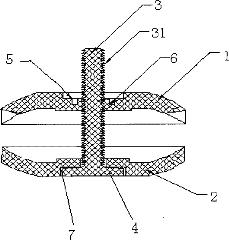
[0018] A skull lock, comprising an upper locking piece 1, a lower locking piece 2 and a lock core 3, the lock core 3 can fix the relative position between the upper locking piece 1 and the lower locking piece 2, and the lock core passes through the lower locking piece 2 and the lower locking piece in turn The upper lock piece 1 and the end of the lock core 3 close to the lower lock piece 2 form a stopper 4 (that is, the big end of the bolt), and the stopper 4 stops on the side of the lower lock piece 2 facing away from the upper lock piece 1, so that one end of the lock cylinder is positioned It is fixed on the lower locking plate, and the outer surface of the lock cylinder is provided with teeth 31 facing the lower locking plate (one-way locking), and the teeth on the outer surface of the lock cylinder are clamped in the upper locking plate to enhance the locking force. The uniformity of locking force and the quickness of locking can reduce the operation time.

[0019] The ou...


PUM


Abstract

The invention discloses a skull lock, which comprises an upper lock piece, a lower lock piece and a lock core, the lock core can fix the relative position between the upper lock piece and the lower lock piece, and the lock core passes through the lower lock piece and the upper lock piece in turn , the end of the lock cylinder close to the lower lock piece forms a stopper, which is the big end of the bolt, and the stopper stops on the side of the lower lock piece back to the upper lock piece, so that one end of the lock cylinder is fixed on the lower lock piece, and the outer surface of the lock cylinder There are teeth facing the lower lock plate, and the teeth on the outer surface of the lock cylinder are clamped into the upper lock plate, so as to enhance the locking force, the uniformity of the locking force and the quickness of locking, and reduce the operation time. The skull lock has a simple structure, can be quickly locked, has a better locking effect, and is not easy to fall off.

Description

technical field [0001] The invention relates to a medical skull lock. Background technique [0002] In cranial surgery, a cranial lock is often required. At present, most of the used cranial locks use threaded fastening to lock the two locking plates, so as to achieve the purpose of fixing the skull. This locking method not only takes a long time for the operation, but also because the locking plate is relatively thin and there are few locking threads, it is easy to cause the locking plate to fall off, which affects the operation effect, and seriously requires a second operation, which brings greater pain to the patient. Contents of the invention [0003] In order to overcome the above-mentioned defects, the present invention provides a skull lock, which has a simple structure, can be quickly locked, has a better locking effect, and is not easy to fall off. [0004] The technical scheme adopted by the present invention in order to solve its technical problems is: a kind ...

Claims


Application Information

Patent Timeline
Patent Type & Authority Applications(China)
IPC IPC(8): A61B17/68
Inventor 葛建伟
Owner SUZHOU SHIP BIOLOGICAL TECH
Why Eureka
Try Eureka