
Tire bead coils

A technology of bead rings and disks, which is applied to tires, manufacturing rings from wires, and other household appliances. It can solve the problems of low work efficiency and high scrap rate, and achieve the goals of reducing scrap rate, improving work efficiency, and eliminating misoperation. Effect

Inactive Publication Date: 2011-12-28
AEOLUS TIRE
View PDF5 Cites 8 Cited by
  • Summary
  • Abstract
  • Description
  • Claims
  • Application Information

AI Technical Summary

Problems solved by technology

[0003] The technical problem to be solved by the present invention is that the seam meshing opening of the steel wire rolled into a coil is easy to dislocate the steel wire, resulting in a high scrap rate and low work efficiency, and provides a tire bead coil rolled into a coil with a low scrap rate and high work efficiency

Method used


Image

  • Tire bead coils
  • Tire bead coils
  • Tire bead coils

Examples


Embodiment 1

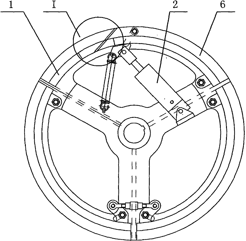
[0019] Such as figure 1 , 2 , 5 and 6, the present invention includes a fixed leaf 1 rolled into a disk and a movable leaf 6 rolled into a disk, and the fixed leaf 1 rolled into a disk and the movable leaf 6 rolled into a disk have a stepped cross section, wherein the lower end of the step is a winding disk 4. The upper end of the step is a flange 5, and the meshing opening 3 between the fixed vane 1 and the movable leaf 6 is a staggered joint, and the staggered joint refers to the staggered joint at the 3rd joint. The meshing surface of the blue disk 5 is different from the meshing surface of the winding disk 4 (that is, they are not on the same plane). The staggered distance L of the engaging openings 3 is 25-35 mm. Say 25, 27, 28, 30, 32, 34 or 35mm.

[0020] The working process of the present invention is as follows: start the cylinder 2, and the cylinder 2 drives the movable blade 5 of the coiled disc to move, so that the meshing port 3 is opened. The meshing surface ...

Embodiment 2

[0022] Such as Figure 7 As shown, there are two winding disks 4, and the meshing surfaces of two adjacent winding disks 4 are different from each other. In this embodiment, different winding disks 4 have different diameters, and travellers with different diameters can be wound, which is convenient and convenient to use. When winding, the lowermost winding disk 4 can be positioned by means of the side of the upper winding disk 4, and since the engaging surfaces of two adjacent winding disks 4 are not on the same plane, misoperation will not occur. Or three or four of the winding discs 4 . The staggered distance L between two adjacent surfaces at the meshing opening 3 is 25-35 mm. Say 25, 27, 28, 30, 32, 34 or 35mm.

[0023] In the above-mentioned embodiments, the engaging surface 3 is a zigzag engaging.


PUM


Abstract

The invention discloses a tire bead ring rolled into a disk, which belongs to the field of tire preparation. Including the fixed leaf rolled into a disk and the movable leaf rolled into a disk, the cross section of the fixed leaf rolled into a disk and the movable leaf rolled into a disk is stepped, the lower end of the step is a winding disk, the upper end of the step is a flange, and the fixed leaf is rolled into a disk and fixed The meshing opening between the blade and the movable blade fixedly rolled into a disc is a staggered jaw, and the staggered jaw means that at the meshing opening, the meshing surface of the flange plate is different from the meshing surface of the winding disk. In the present invention, the meshing opening is a staggered seam structure. When the steel wire is clamped, the side of the flange plate on the coiled body is used for positioning, so that the steel wire is accurately attached to the working surface of the coiled body, eliminating the need for The misoperation phenomenon in the winding process of the traveler reduces the scrap rate, and the scrap rate caused by misoperation is almost zero, which improves the work efficiency.

Description

technical field [0001] The invention belongs to the field of tire preparation, and in particular relates to a tire bead ring rolled into a coil. Background technique [0002] The zigzag meshing opening between the movable leaf and the fixed leaf of the existing tire bead is rolled into a disk, such as the authorized announcement number is "CN2442833Y", the application number is "00248862.0", and the name is As described in the invention patent of "tire bead rolled into a coil", and as attached figure 1 , 3 Shown in and 4, the cross-section of the fixed leaf and movable leaf rolled into a disc is stepped, wherein the lower end of the step is a winding disc 4, on which steel wire is wound, and the upper end of the step is a flange 5, which is used to fix the coiled disc. The said seam gap means that the meshing surface of the winding disc 4 at the meshing opening 3 and the meshing surface of the flange 5 are on the same plane. Since the interface of the wire rope is at the ...

Claims


Application Information

Patent Timeline
IPC IPC(8): B21F37/00B29D30/48
Inventor 张陆军贾继斌李国利刘磊许庆彬申玉德
Owner AEOLUS TIRE
Learn More