an engine connecting rod

A technology of engine connecting rod and connecting rod body, which is applied to connecting rods, mechanical equipment, shafts and bearings, etc. It can solve the problems of weak fixing, easy wear and deviation, and achieve the effect of rich structural changes and improved accuracy.

Inactive Publication Date: 2011-12-28
钟树平
View PDF4 Cites 6 Cited by
  • Summary
  • Abstract
  • Description
  • Claims
  • Application Information

AI Technical Summary

Problems solved by technology

[0003] The technical problem to be solved by the present invention is to provide a new type of engine connecting rod for the existing technical pro

Method used


Image

  • an engine connecting rod
  • an engine connecting rod
  • an engine connecting rod

Examples


Embodiment approach 1

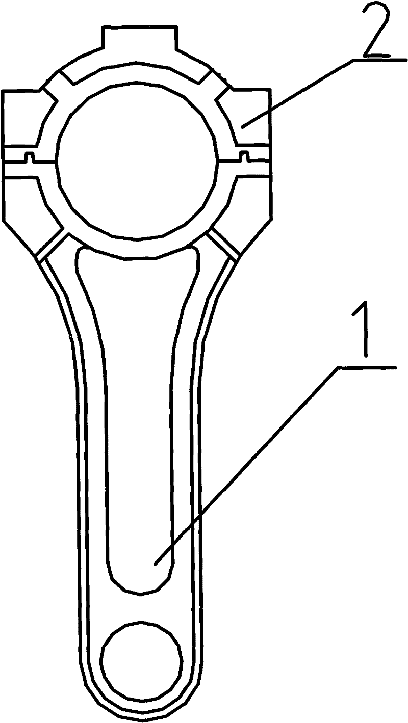
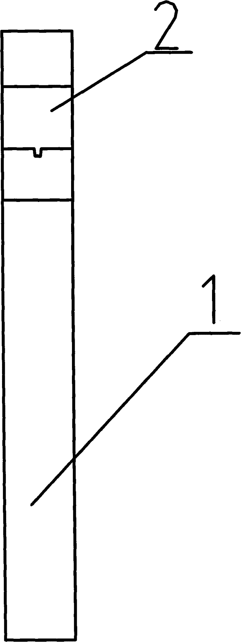
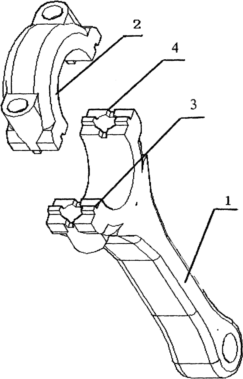
[0020] combine figure 1 , figure 2 , image 3 and Figure 4 , an engine connecting rod, comprising a connecting rod body 1 and a connecting rod cover 2, bolts are used between the connecting rod body 1 and the connecting rod cover 2, and the mating surface of the connecting rod body 1 and the connecting rod cover 2 is set There are intersecting and corresponding convex teeth 3 and grooves 4, and the connecting rod body 1 and the connecting rod cover 2 are connected by crossing and corresponding convex teeth 3 and grooves 4; the convex teeth 3 and grooves 4 form a cross shape; the connecting rod body 1 and the connecting rod cover 2 are meshed and connected by cross-shaped convex teeth 3 and grooves 4, and then fixed by bolts, so that all directions between the mating surfaces can be Fixed by intersecting convex teeth 3 and grooves 4, there will be no sliding of the connecting rod body 1 and the connecting rod cover 2 in the plane direction of the mating surface, avoiding t...

Embodiment approach 2

[0022] combine Figure 5 , the intersecting protruding teeth 3 and grooves 4 on the mating surfaces of the connecting rod body 1 and the connecting rod cover 2 can be multiple; Figure 5 There are multiple convex teeth 3 and grooves 4 shown, and the connecting rod body 1 and the connecting rod cover 2 are meshed and connected by multiple convex teeth 3 and grooves 4, and then fixed by bolts so that the mating surface is in the plane direction All directions above can also be fixed by the protruding teeth 3 and grooves 4, so that the sliding of the connecting rod body 1 and the connecting rod cover 2 in the plane direction of the mating surface will not occur, and the contact between the connecting rod body 1 and the connecting rod cover 2 will not be avoided. The relative motion ensures the motion accuracy with the crankshaft, and further improves the reliability, durability and safety of the engine connecting rod; the meshing connection of multiple convex teeth 3 and grooves ...

Embodiment approach 3

[0024] combine Figure 6 , the protruding teeth 3 and grooves 4 on the connecting rod body 1 and the connecting rod cover 2 are mutually intersecting, Figure 6 What is shown is that the protruding teeth 3 and the grooves 4 are intersected with each other; the connecting rod body 1 and the connecting rod cover 2 are meshed and connected by the protruding teeth 3 and the grooves 4 intersecting each other, and then fixed by bolts so that they fit together All directions between the surfaces can be fixed by intersecting protruding teeth 3 and grooves 4, so that there will be no sliding of the connecting rod body 1 and the connecting rod cover 2 in the plane direction of the mating surface, and avoiding the connection between the connecting rod body 1 and the connecting rod cover 2. The relative movement of the connecting rod cover 2 ensures the movement accuracy with the crankshaft, and further improves the reliability, durability and safety of the engine connecting rod; the inte...


PUM


Abstract

The invention discloses an engine connecting rod, which comprises a connecting rod body and a connecting rod cover, and the connecting rod body and the connecting rod cover are fixed by bolts. The connecting rod body and the connecting rod cover are provided with mutually intersecting and corresponding convex teeth and grooves, and the connecting rod body and the connecting rod cover are positioned and connected by engaging the convex teeth and the grooves; A cross shape is formed between the grooves; the convex teeth can be involute teeth, trapezoidal tooth shapes, arc tooth shapes or other arbitrary polygonal and arc tooth shapes, and the grooves are some kind of teeth corresponding to the convex teeth shape; the intersecting protruding teeth and grooves on the connecting rod body and the connecting rod cover can be multiple; the beneficial effects of the present invention: the structure changes are rich, and corresponding structures can be set according to different needs; At the same time, the reliability, durability and safety of the engine connecting rod are further improved.

Description

technical field [0001] The invention relates to a sliding plug engine, an air compressor, in particular to a connecting rod for an automobile engine. Background technique [0002] The quality of the engine is a very important indicator in the judgment of car performance. In the engine, it is necessary to transmit power through the connecting rod installed in the engine. There are various connecting rod structures on the market now, but the structure of the connecting rod itself is relatively simple. The engine connecting rod is mainly connected by the connecting rod body and the connecting rod cover through bolts. Simple bolt fixed connection, the mating surface between the connecting rod body and the connecting rod cover is prone to loosening, and the fixing is not firm, especially when the connecting rod is reciprocating for a long time under the condition of such a powerful engine, the connecting rod body The mating surface with the connecting rod cover is easy to wear ...

Claims


Application Information

Patent Timeline
IPC IPC(8): F16C7/02
Inventor 钟树平
Owner 钟树平
Why Eureka
Try Eureka