Bi-directional heat sink for packaging components and assembly method thereof

A technology of packaging components and assembly methods, which is applied in the direction of electrical components, electric solid-state devices, semiconductor devices, etc., and can solve problems such as difficulty in obtaining heat dissipation, difficulty in installing and inserting printed circuit boards, high material costs, and labor hours.

Inactive Publication Date: 2011-12-28
DELTA ELECTRONICS (SHANGHAI) CO LTD
View PDF5 Cites 9 Cited by
  • Summary
  • Abstract
  • Description
  • Claims
  • Application Information

AI Technical Summary

Problems solved by technology

[0004] The above two assembly methods of IC components 4a, 4b need to be assisted by metal clips 1a or plastic clips 1b, and assembled with screws 2a, 2b and heat sinks 3a, 3b, locked first and then inserted in a single workpiece. The printed circuit boards 5a, 5b, but because the IC components 4a, 4b are highly integrated and small-volume electronic parts, have a precise and compact structure and poor compressive strength, the products assembled by the above-mentioned traditional method have the following problems:
[0005] 1. Visible and invisible damage and potential quality risks are easily caused by external force, which will directly lead to damage of IC components 4a and 4b and seriously affect the life of the product, and it is not easy to inspect and control the quality
[0006] 2. IC components 4a, 4b only contact the heat sink 3a, 3b on the mounting surface, so that the IC components 4a, 4b conduct heat dissipation only through one side of the contact surface, and it is difficult to obtain an ideal heat dissipation effect, which will affect the quality and functional stability of electrical products sex
[0007] 3. Due to the need for fixture assistance and assembly with screws, higher material costs and labor hours are required
When a plurality of transistor parts and IC components 4a, 4b are locked on the heat sinks 3a, 3b at the same time, it is difficult to all align with the holes of the printed circuit boards 5a, 5b due to the many pins, so that the printed circuit boards 5a, 5b are inserted into the printed circuit boards 5a, 5b 5b becomes quite difficult
Once the soldering operation is done, it is difficult to repair if the wire pins are not aligned with the holes of the printed circuit board 5a and 5b during the test.

Method used


Image

  • Bi-directional heat sink for packaging components and assembly method thereof
  • Bi-directional heat sink for packaging components and assembly method thereof
  • Bi-directional heat sink for packaging components and assembly method thereof

Examples


Embodiment Construction

[0047] The detailed description and technical content of the present invention are described below with the drawings, but the drawings are only for reference and illustration, and are not intended to limit the present invention.

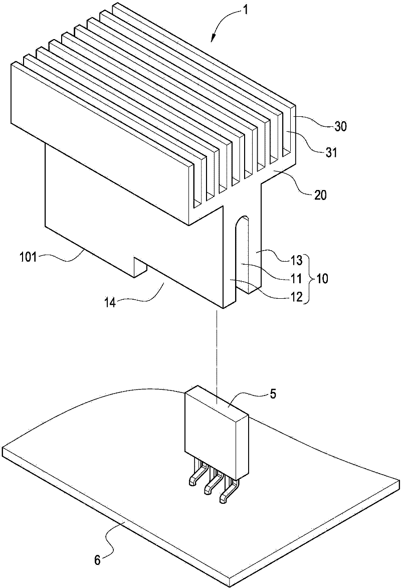
[0048] see image 3 Figure 3 to Figure 5 As shown, the present invention provides a bidirectional heat sink for packaging components. This bidirectional heat sink 1 is made of metal materials such as aluminum, copper or alloys thereof, and mainly includes a first heat dissipation plate 10, a second The cooling plate 20 and a plurality of cooling fins 30 .

[0049] The first heat dissipation plate 10 of this embodiment is roughly in the shape of a vertical rectangle, but it is not limited to this shape, and it can also be in various other geometric shapes, and a groove 11 is opened in the middle of the first heat dissipation plate 10 , and the first cooling plate 10 forms two partition walls 12 , 13 on both sides of the channel 11 .

[0050] The s...


PUM


Abstract

The invention provides a bidirectional radiator used for a packaged component and an assembly method thereof. The bidirectional radiator comprises: a first heat sink, a second heat sink and a plurality of radiating fins. The first heat sink is provided with a channel and dividing walls are arranged on two sides of the channel. The packaged component is embedded in the channel and contacts with the dividing walls. The second heat sink extends along one end of the first heat sink. The radiating fins are respectively extended out of the second heat sink along a direction of being far from the first heat sink. Thereby, a cooling surface area contacting with the packaged component can be increased so that a cooling efficiency can be improved. And a stable assembly and rapid combination can be reached.

Description

technical field [0001] The invention relates to a heat sink, in particular to a bidirectional heat sink for packaging components and an assembly method thereof. Background technique [0002] Integrated Circuit (IC) components are widely used in modern electrical products. With the widespread application of information electronic products, the technical capabilities of R&D and design are also increasing. Taking information electronic products as an example, the integration level of IC components is increasing day by day, and their functional pins are many and small. IC component manufacturers continue to reduce the area of ​​IC components to reduce their volume in order to improve product performance and price ratio. Therefore, IC components, which are high-performance and high-power components, must first solve their assembly processing and heat dissipation problems. [0003] Traditional assembly methods are mainly solutions provided by IC component manufacturers, where fi...

Claims


Application Information

Patent Timeline
Patent Type & Authority Applications(China)
IPC IPC(8): H01L23/367H01L21/50
CPCH01L23/367H01L2924/0002Y10T29/49826H01L2924/00
Inventor 李卫国何乐星
Owner DELTA ELECTRONICS (SHANGHAI) CO LTD
Why Eureka
Try Eureka