
Heat dissipation device of sealed case and sealed case

A heat dissipation device and a sealed technology, which is applied in the directions of sealed shell, cooling/ventilation/heating transformation, electrical components, etc., can solve the problems of high noise of the chassis, inability to prevent dust and moisture, and low heat dissipation efficiency of the chassis

Pending Publication Date: 2019-11-05
KYLAND TECH CO LTD +1
View PDF0 Cites 5 Cited by
  • Summary
  • Abstract
  • Description
  • Claims
  • Application Information

AI Technical Summary

Problems solved by technology

Because this technology requires the cooling fan to rotate at high speed and the heating electronic components are directly connected to the outside air, the noise of the chassis is relatively large, the chassis of the equipment is not sealed, and it cannot be dust-proof and moisture-proof, which seriously affects the performance and performance of the electronic components in the chassis. life
[0003] The heat dissipation of the chassis of the existing sealed electronic equipment mostly adopts the method of increasing the cooling area and surface area of ​​the chassis, increasing the size of the chassis, making the chassis bulky, heavy, and costly, resulting in unnecessary waste
Moreover, the heat dissipation efficiency of the chassis of the existing sealed electronic equipment is low, and the temperature inside the chassis is high, which seriously restricts the improvement of the performance of the corresponding equipment and the selection of electronic components in the chassis

Method used


Image

  • Heat dissipation device of sealed case and sealed case
  • Heat dissipation device of sealed case and sealed case
  • Heat dissipation device of sealed case and sealed case

Examples


Embodiment Construction

[0033] In order to make the technical problems solved by the present invention, the technical solutions adopted and the technical effects achieved clearer, the technical solutions of the embodiments of the present invention will be further described in detail below in conjunction with the accompanying drawings. Obviously, the described embodiments are only the technical solutions of the present invention. Some, but not all, embodiments. Based on the embodiments of the present invention, all other embodiments obtained by those skilled in the art without making creative efforts belong to the protection scope of the present invention.

[0034] In the description of the present invention, unless otherwise clearly specified and limited, the terms "connected", "connected" and "fixed" should be understood in a broad sense, for example, it can be a fixed connection, a detachable connection, or an integrated ; It can be a mechanical connection or an electrical connection; it can be a d...


PUM


Abstract

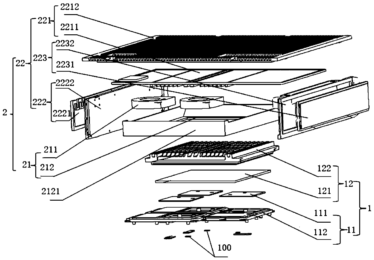
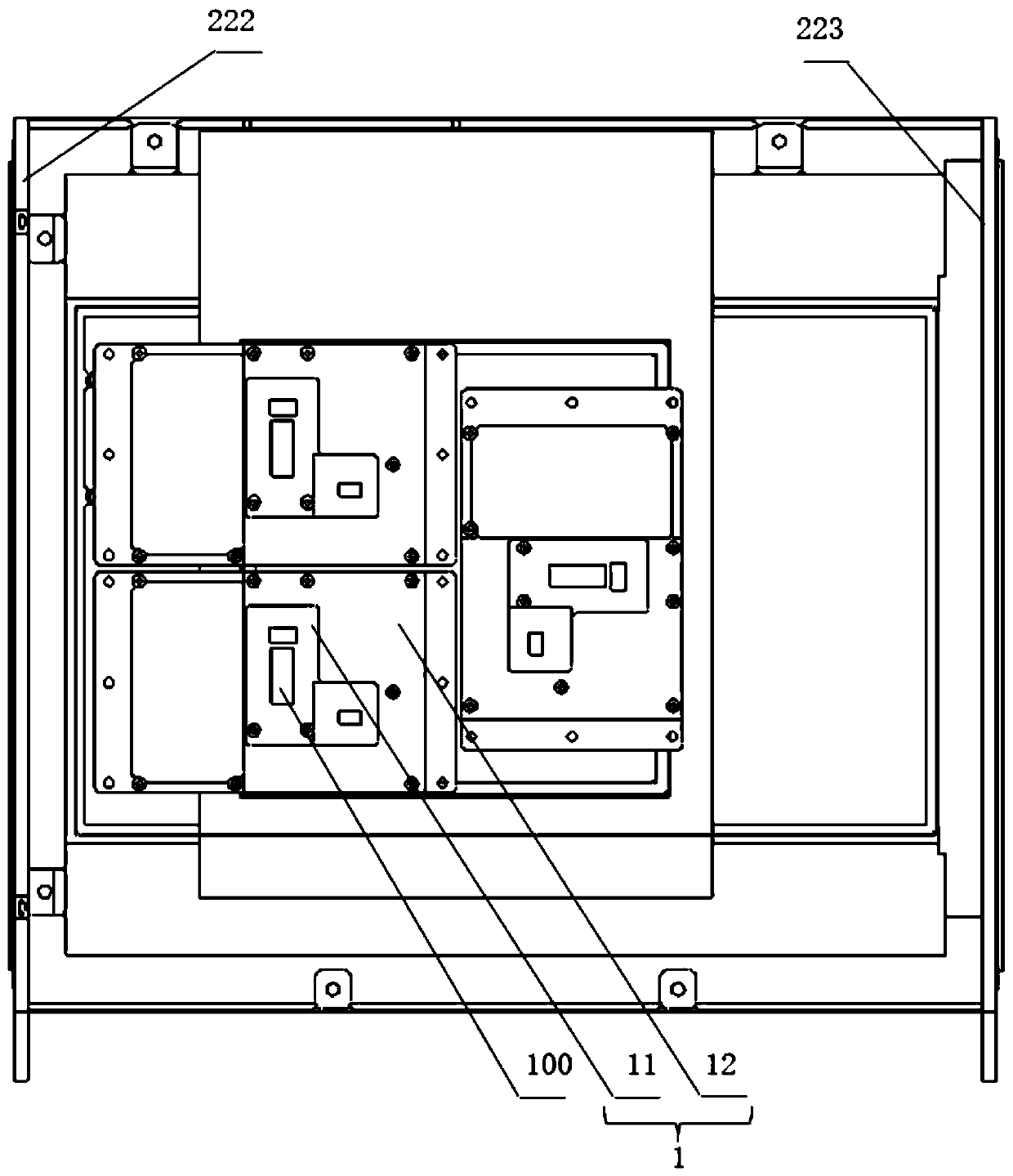
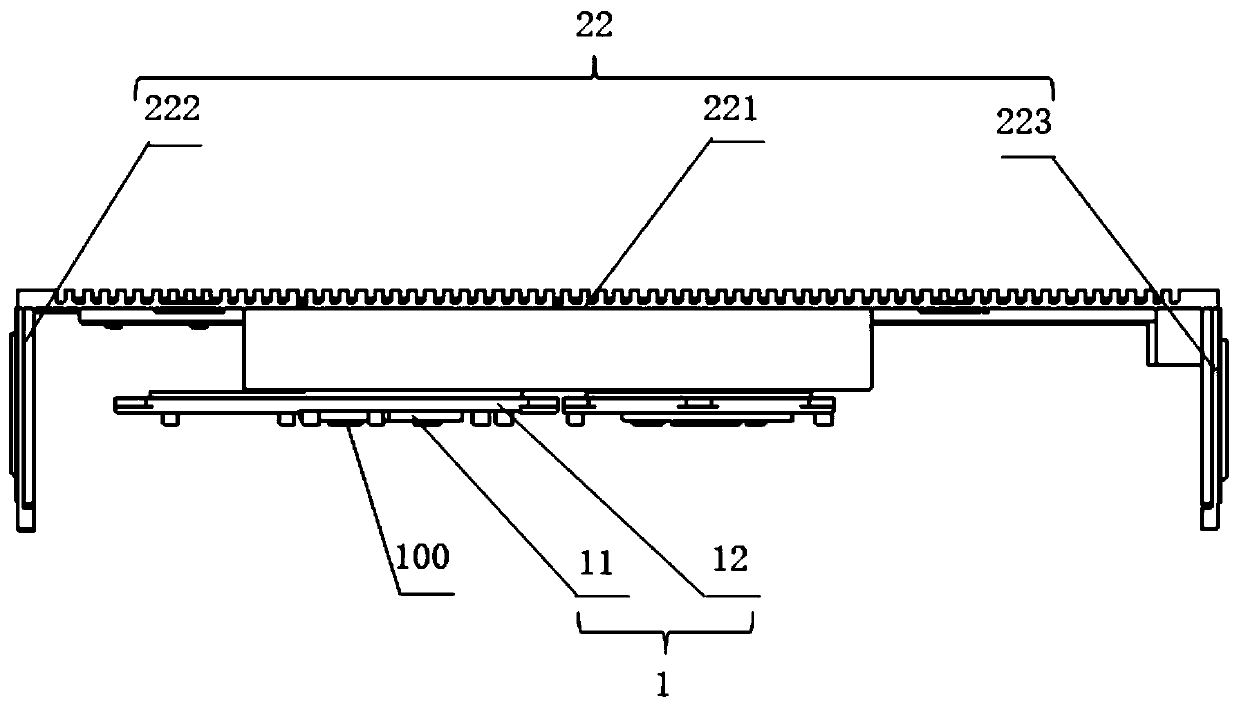
The invention relates to the technical field of heat dissipation, and discloses a heat dissipation device of a sealed case and the sealed case. The heat dissipation device, which is used to dissipatethe heat of heating electronic components installed in the case, includes an internal heat transfer system and an external heat transfer system. The internal heat transfer system is located in the sealed case and is in butt joint with the heating electronic components, and the heat generated by the heating electronic components can be transferred to the internal heat transfer system. The externalheat transfer system includes a blowing part and heat dissipation cover plates. The heat dissipation cover plates are all made of vapor chambers, and the blowing part is arranged on the inner side ofthe heat dissipation cover plates. The external heat transfer system is used to transfer the heat outside a sealed area to the outside air. The heat dissipation cover plates are connected with one another, can transfer heat to one another and are used to transfer heat to the outside air. The heat dissipation device of the sealed case in the invention has high heat dissipation efficiency, can reduce the internal temperature of the sealed case, improves the performance of the sealed case and increases the optional selectivity of the electronic components in the case.

Description

technical field [0001] The invention relates to the technical field of heat dissipation, in particular to a heat dissipation device for a sealed chassis and a sealed chassis. Background technique [0002] At present, the chassis of the existing electronic equipment mostly adopts a fan to perform forced convection to dissipate heat. The heat dissipation fan is installed in the chassis, and blows the external air to the heating electronic components through forced convection, so as to realize the heat exchange between the heating electronic components and the external air. Because this technology requires the cooling fan to rotate at high speed and the heating electronic components are directly connected to the outside air, the noise of the chassis is relatively large, the chassis of the equipment is not sealed, and it cannot be dust-proof and moisture-proof, which seriously affects the performance and performance of the electronic components in the chassis. life. [0003] T...

Claims


Application Information

Patent Timeline
IPC IPC(8): H05K7/20H05K5/06
CPCH05K7/20436H05K7/20154H05K5/069
Inventor 张航天
Owner KYLAND TECH CO LTD
Learn More