Automatic paper feeding scanning device

A technology of automatic paper feeding device and scanning device, which is applied in the direction of image communication, electrical components, etc., can solve the problems of degumming, shortening the service life of automatic paper feeding scanning device, and the inability of the scanning module 3 to move smoothly to the bottom of the document platform 11, etc., to achieve Prevent impact, ensure service life, and ensure the effect of scanning quality

Inactive Publication Date: 2011-12-28
PRIMAX ELECTRONICS LTD
View PDF6 Cites 0 Cited by
  • Summary
  • Abstract
  • Description
  • Claims
  • Application Information

AI Technical Summary

Problems solved by technology

The frame 13 that fixes the glass plate 12 is generally made of plastic and has a protrusion 13a. When the scanning module 3 moves under the glass plate 12, the plastic deformation of the frame 13 may cause the scanning module 3 to collide when moving. to the protruding portion 13a, causing the scanning module 3 to fail to move smoothly to the bottom of the document platform 11 for scanning operations
However, if the protrusion 13a is removed and the glass plate 12 is directly bonded to the vertical wall 13b of the frame 13, although the problem of moving the scanning module 3 can be solved, the glass plate 12 will lose the support of the protrusion 13a, and debonding will occur after long-term use. problem, so as to shorten the service life of the auto-feed scanning unit

Method used


Image

  • Automatic paper feeding scanning device
  • Automatic paper feeding scanning device
  • Automatic paper feeding scanning device

Examples


Embodiment Construction

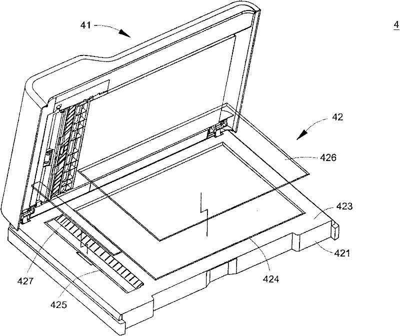
[0028] The present invention proposes an automatic paper-feed scanning device, which solves the problems caused by the prior art by changing the combination of the second light-transmitting plate and the second scanning window for paper-feed scanning. see image 3 and Figure 4 , image 3 It is a partially decomposed three-dimensional structural schematic diagram of the first preferred embodiment of the automatic paper-feeding scanning device of the present invention, Figure 4 It is a front sectional schematic diagram of the first preferred embodiment of the automatic paper feeding scanning device of the present invention. In addition, in order to clearly express the paper feeding path, Figure 4 and Figure 5 The drawing of the paper feed roller will be omitted in .

[0029] Please refer to image 3 and Figure 4 , the automatic paper feeding scanning device 4 includes an automatic paper feeding device 41 and a flatbed scanner 42 disposed below the automatic paper fee...


PUM


Abstract

The invention provides an automatic paper feeding scanning device. The automatic paper feeding scanning device includes an automatic paper feeding device and a flatbed scanner. The platform scanner includes a housing, a scanning module and a scanning platform, and the scanning platform has a first scanning window and a second scanning window, which are used to fix the first light-transmitting plate and the second light-transmitting plate respectively, wherein the second scanning window The inner edge is complementary to the side edge of the second transparent plate. The present invention has the advantages of preventing the scanning module from being impacted while moving and preventing dust from falling into the housing.

Description

technical field [0001] The invention relates to a scanning device, in particular to an automatic paper-feeding scanning device. Background technique [0002] Various machines equipped with an automatic paper feeding device to provide an automatic paper feeding function, such as printers, scanners, fax machines, etc., have become common peripheral devices for computers. Such as figure 1 as shown, figure 1 It is a front sectional view of an existing automatic paper feeding scanning device. The existing automatic paper feeding scanning device 1 includes an automatic paper feeding device 1 a and a scanning device 1 b, wherein the automatic paper feeding device 1 a is installed on the upper cover 2 . The automatic paper feeder 1a has a paper feed outlet 14 for feeding paper out of the automatic paper feeder 1a. [0003] The scanning device 1b includes a scanning housing 10, a light-transmitting platform 11, a glass plate 12, a frame 13 and a scanning module 3, wherein the scan...

Claims


Application Information

Patent Timeline
Patent Type & Authority Applications(China)
IPC IPC(8): H04N1/04
Inventor 徐维燻
Owner PRIMAX ELECTRONICS LTD
Why Eureka
Try Eureka